Started: March 2016
Completed: July 2016
Released: November 2016
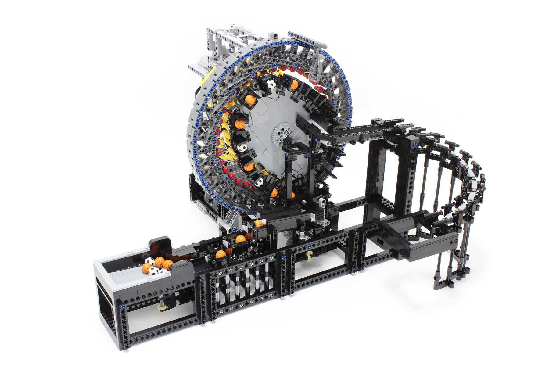
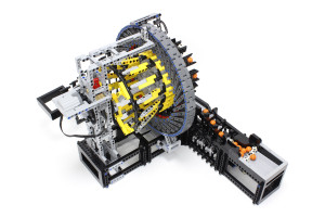
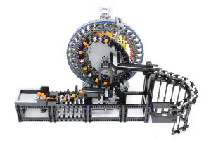
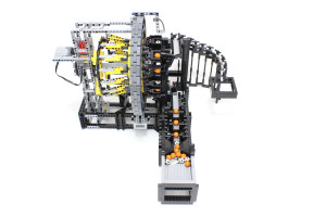
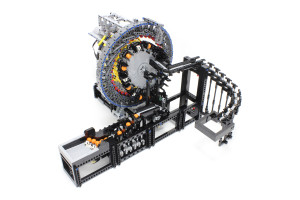
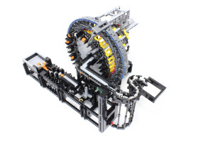
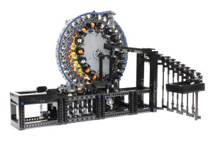
This great ball contraption (GBC) module utilizes the concept of strain wave gearing. The module is based on the strain wave gearing model I made in 2012. Strain wave gearing is often used for industrial purposes, with such products famously manufactured by Harmonic Drive Systems Inc. Although I had the idea of applying the aforementioned mechanism to the GBC module for quite some time, it took a long time to complete the model due to the engineering challenges involved.
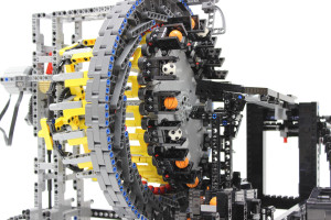
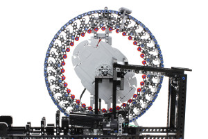
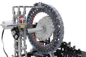
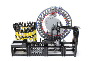
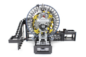
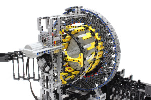
Strain wave gearing consists of three components: a wave generator, a flex spline, and a circular spline. Wave generator, flex spline, and circular spline can be recognized as the light bluish ellipse in the center, the yellow cup, and the dark bluish gray outer ring, respectively, in the GBC module.
The number of teeth on the flex spline and circular spline are 32 and 36, respectively. The reduction ratio is calculated using the following formula:
Reduction ratio = (circular spline teeth – flex spline teeth)/flex spline teeth
= (36 – 32)/32
= 1/8.
The wave generator is used as the input, and the flex spline is used as the output.
When the mechanism of interest was applied to the GBC module, the desire was for the movement of the balls to resemble that of the mechanism. I used wave motion of the flex spline to transfer the balls in order to use the strain wave gearing mechanism in GBC module. This differs from the actual strain wave gearing that uses only the reduced rotation of the flex spline as the output.
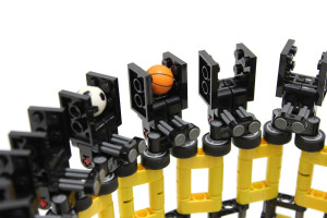
The chucks attached to the front-facing edge of the flex spline are used to grasp the balls. The balls move in tandem with the wave movement of the flex spline, which is the highlight of the module.
The distance travelled by the flex spline must be equal to the interval distance (4 studs) of the ball chucks when the wave generator has turned 180°. The four-tooth differential between the flex spline and the circular spline meets this requirement.
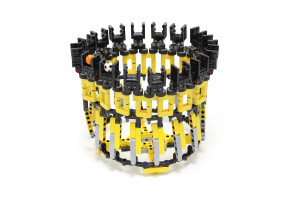
This figure shows the disengaged flex spline. It is necessary for the flex spline to be flexible. The amount of deformation to the flex spline is greater than that of a typical flex spline due to the small reduction ratio of 1/8. The ball joint is used to cope with the large deformation. The deformation capabilities of the Lego assembly allows for a flexible structure. The rollers are attached at the contact point between the flex spline and the wave generator to reduce friction. I focused on making the ball chuck compact. The four-length axle with stop absorbs the deformation of the chuck when grasping a ball.
This image shows the strain wave gearing with the flex spline removed, to show the wave generator and the circular spline clearly. The light bluish ellipse in the center is the wave generator, and the dark bluish gray outer ring is the circular spline.
The red circular components arranged about the inner perimeter of the circular spline function as teeth. These teeth engage with the teeth of the flex spline. The circular spline proved the most difficult component in this GBC module to design. It was necessary for the circular spline to be a rigid structure, in contrast to the flex spline. The circular spline is subjected to inside-out forces. Many prototypes were produced to achieve the desired geometry of the circular spline having the 36 teeth equidistant from one another, while preserving stiffness and aesthetic appeal.
The wave generator is made not using Technic bricks. The ellipse of the wave generator requires accurate adjustment of the major axis length. The major axis length was adjusted to the optimum length using a 1/5 stud. A longer major axis length increases the rotational friction, while a shorter length causes ratcheting.
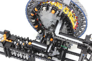
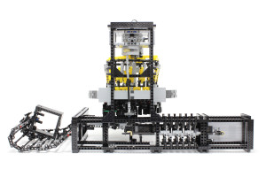
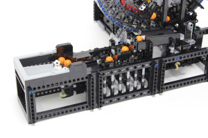
The module has four moving parts: the wave generator, a stopper, a stepper, and an agitator. The stopper is located at the entrance of the wave strain gearing and determines the timing of the ball entry. All moving parts of the module are driven by a single PF XL motor. There is no torque limiter between the motor and the load to secure power transmission.
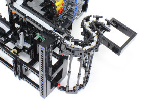
The stepper part of the module is the same design as that of the cycloidal drive GBC module. The slide part of the module is the same design as that of the Fork to Fork GBC module.
The durability of the module has not yet been tested. It is envisaged that the durability of the module will be poor owing to the heavy load on the strain wave gearing.

