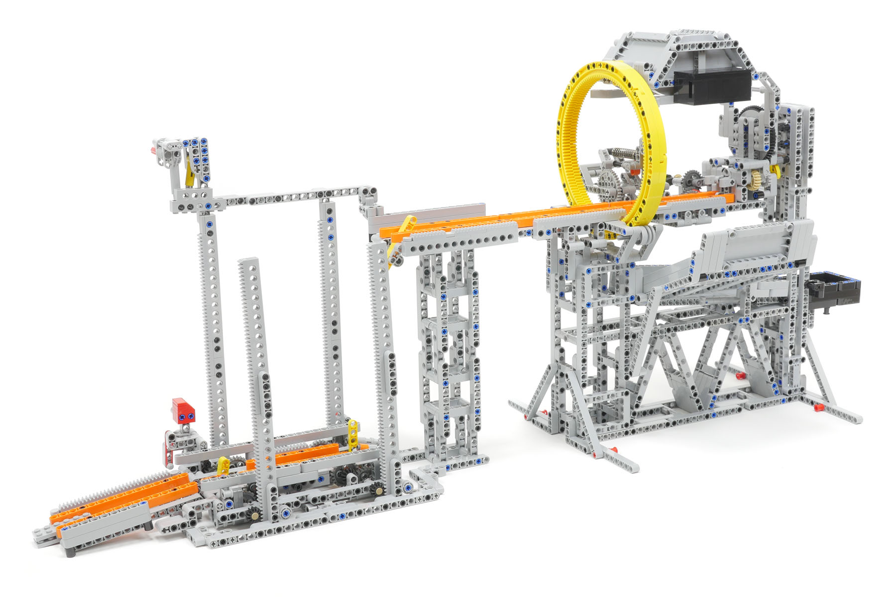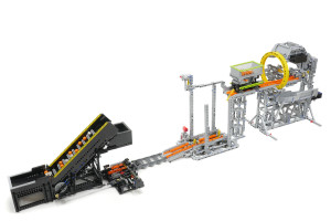
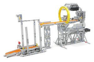
 Rotary dumper module
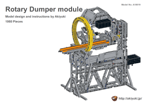
After the train arrives and stays in the module, the track and cylinder that surrounds the train all rotates with the train. During rotation, the balls in the container on the train are unloaded. After rotation, the train starts to leave the module in the reverse direction. The movement of the module is controlled by the motor on the train. The height of the lane to unload the balls is justified to that of the GBC (Great Ball Contraption) standards between the GBC modules so that the module can be connected to the GBC modules.
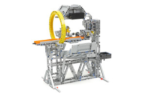
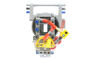
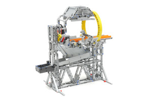 The cam-lock mechanism is adopted in the Rotary dumper module. After the rotation of the track and cylinder surrounding the train, the position of the train should be exactly horizontal. If not, the train cannot move into the Elevator module. After rotation, a semicircular-shaped yellow cam is placed between the two pins, which fixies the track and cylinder in the horizontal position for a certain period of time. Then, the train should be started while the cam-lock is still effective. The timing of the trigger that controls the starting of the train must be adjusted precisely.
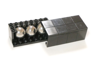
 The black box located at the upper part of the module is a balance weight. The weight is 95g and three steel balls 18mm in diameter can be found inside the box.
 Elevator module
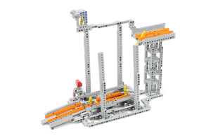
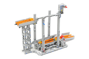
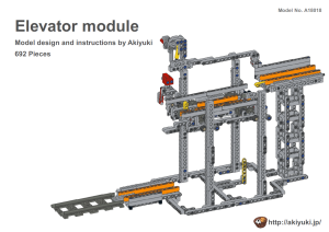
This module performs the function of lifting up the train to the right height to enter the Rotary dumper module. The up and down movement of the Elevator module is controlled by the motor on the train. I spent a lot of time trying to speed up the movement. I first used worm gears to operate the up and down movement. The friction of the worm gears, however, was too large to increase the up and down speed. Then, I developed a gear mechanism that consists of a rack and pinion gear and a reduction spur gear. This attempt to speed up the elevator module is the biggest struggle I faced in developing the railway system. I installed a safety function to prevent the train from falling off the upper track when the track of the elevator module is at the lower position. The yellow-colored parts in the upper track act as a stopper if the train moves ahead on the track at the lower position.
Components of the minimum layout using the Rotary dumper module & Elevator module:
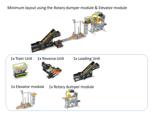
Instructions and MPD files for the components of the minimum layout using the Rotary Dumper module and the Elevator module:
A18010_TrainUnit Instruction [PDF] A18010_TrainUnit [MPD]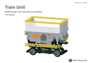 A18011_TrainReverseUnit Instruction [PDF]
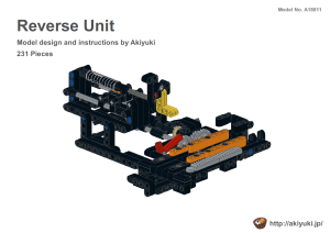
A18011_TrainReverseUnit [MPD]
 A18013_TrainLoaderUnit Instruction [PDF]
A18013_TrainLoaderUnit [MPD]
 A18018_TrainElevator Instruction [PDF]
A18018_TrainElevator [MPD]
 A18019_TrainRotaryDumper Instruction [PDF]
A18019_TrainRotaryDumper [MPD]
 2018/7/16 MPD files were added.
03/22/2018

