Strain Wave Gearing GBC Module

Started: March 2016 Completed: July 2016 Released: November 2016
pw160303r1 pw160307r1 
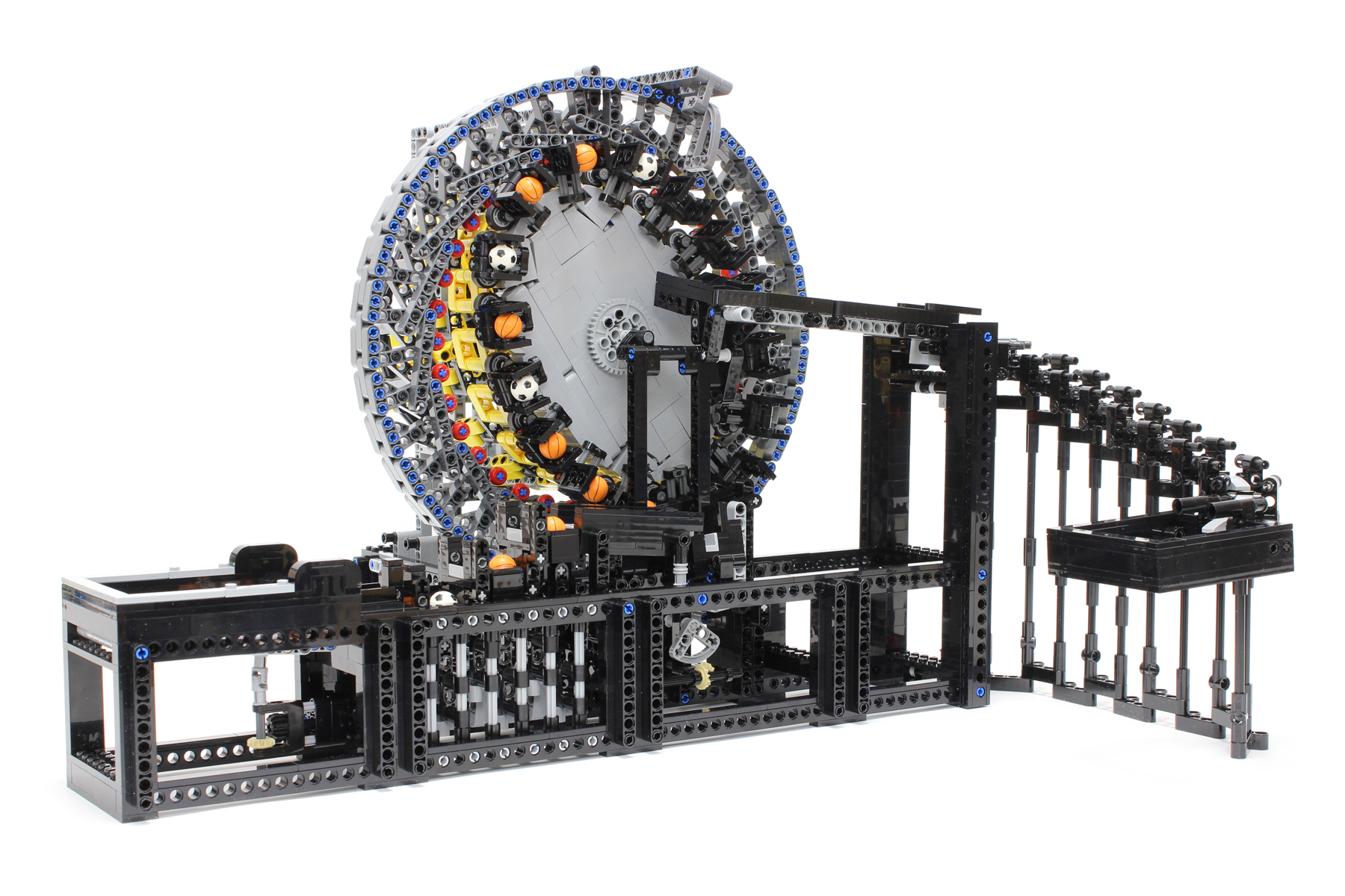
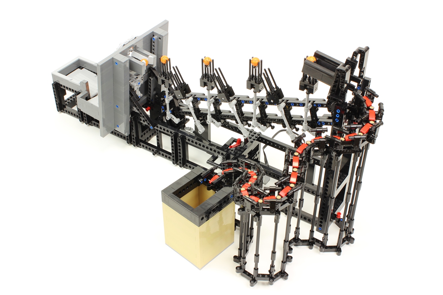
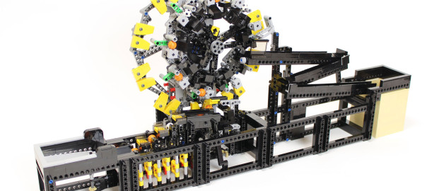
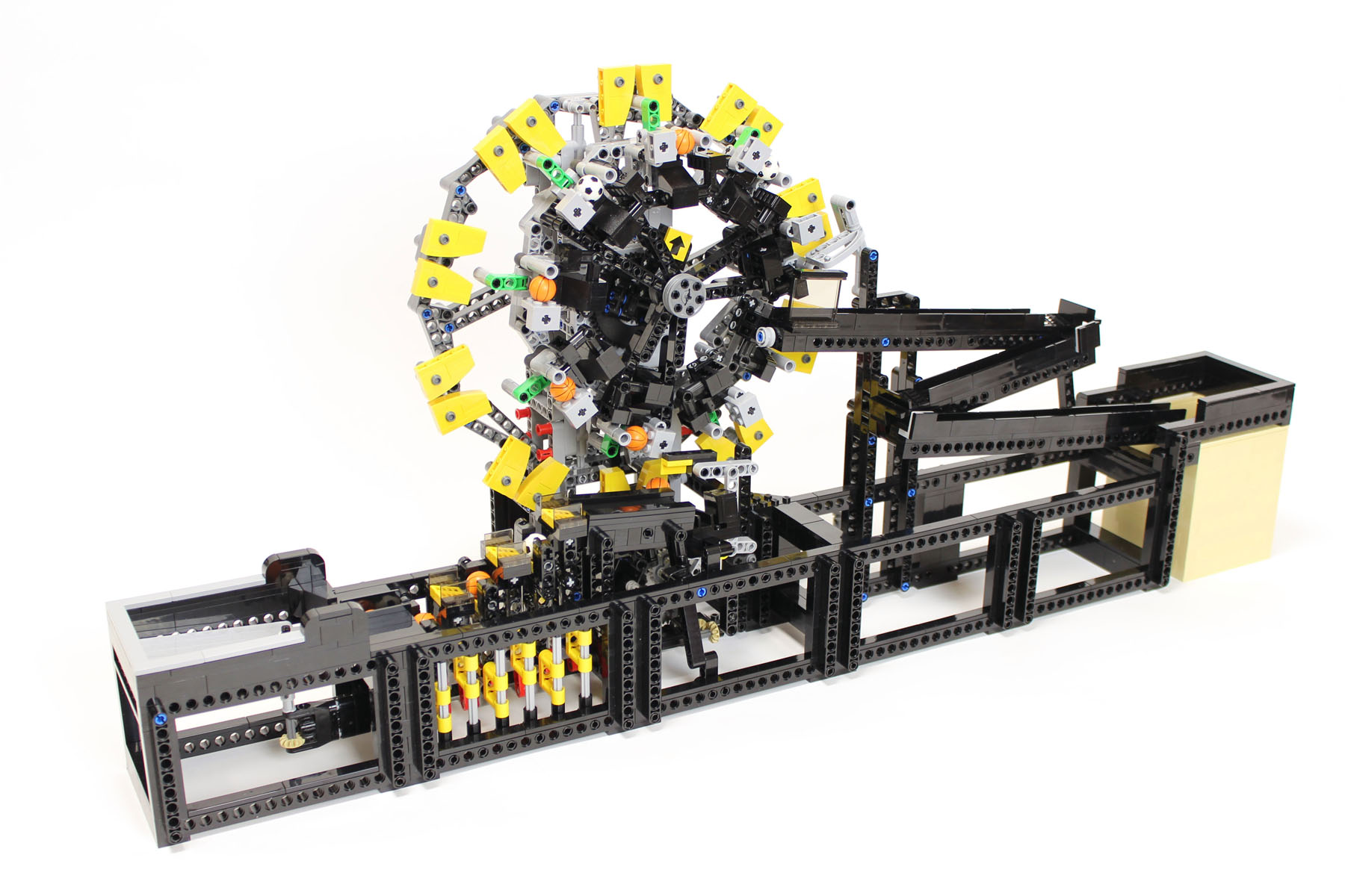
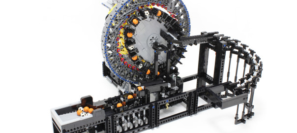
This great ball contraption (GBC) module utilizes the concept of strain wave gearing. The module is based on the strain wave gearing model I made in 2012. Strain wave gearing is often used for industrial purposes, with such products famously manufactured by Harmonic Drive Systems Inc. Although I had the idea of applying the aforementioned mechanism to the GBC module for quite some time, it took a long time to complete the model due to the engineering challenges involved. pw160312r1 pw160301r1 
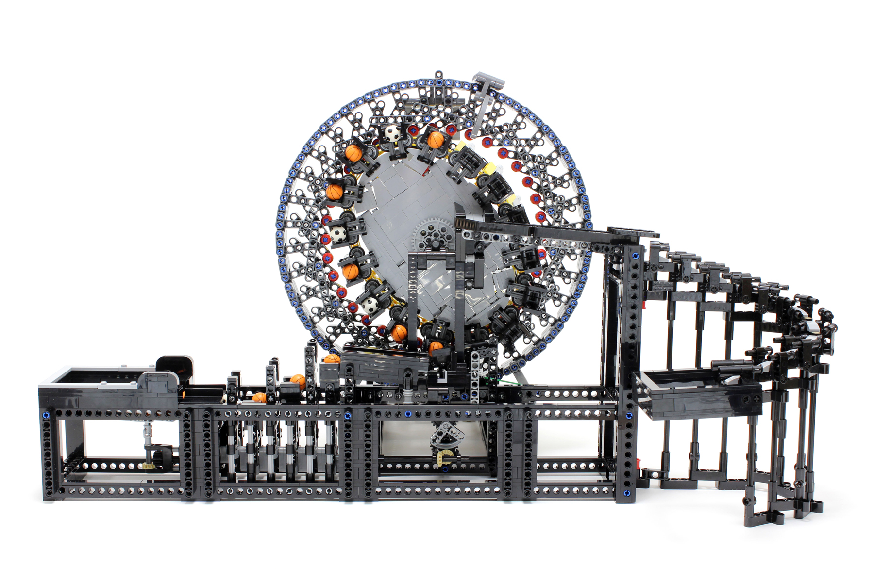
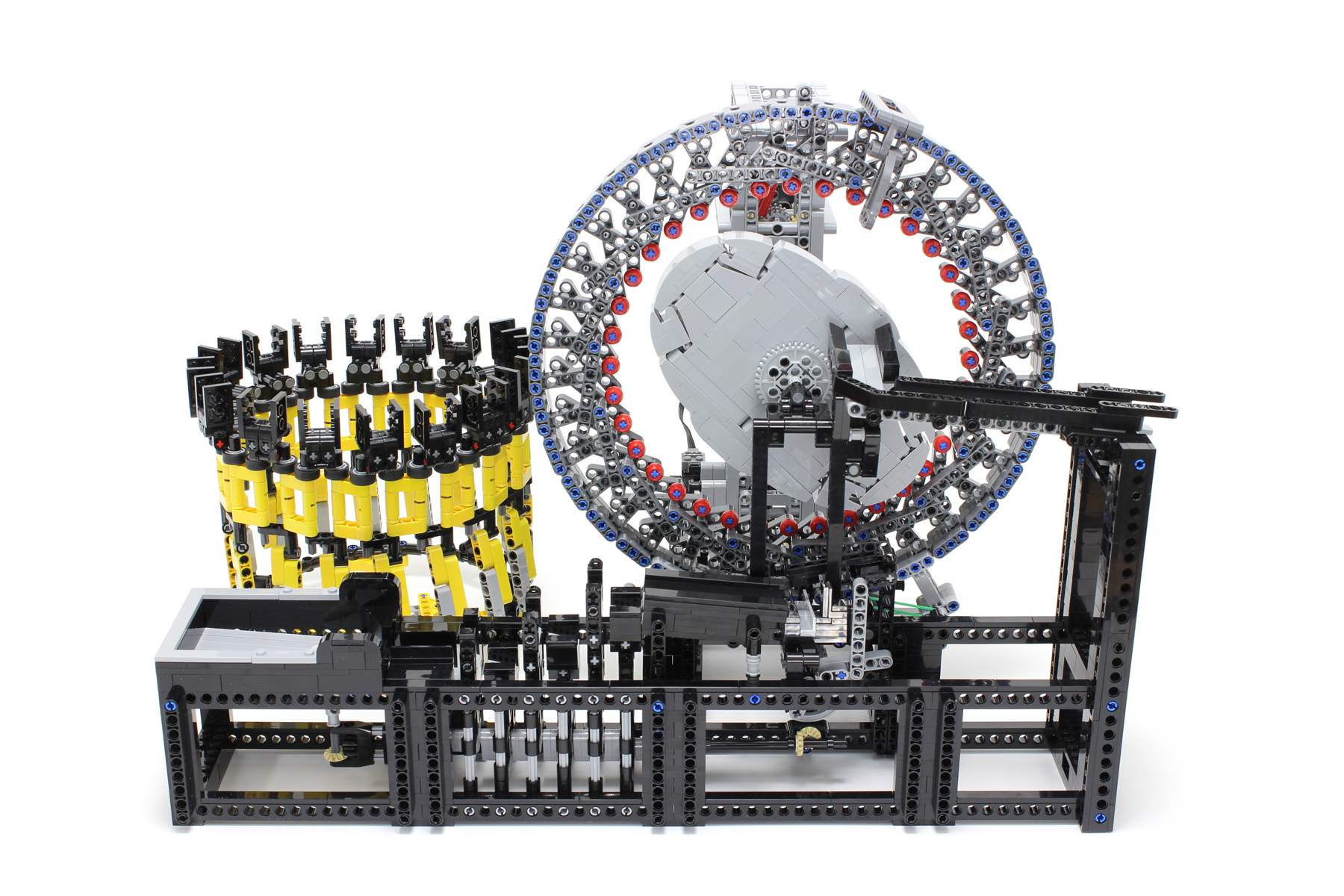
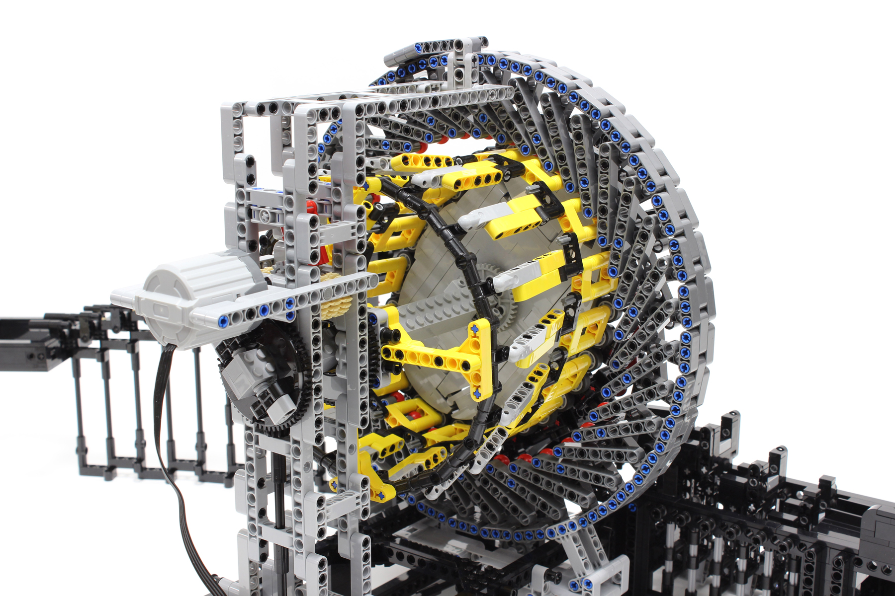
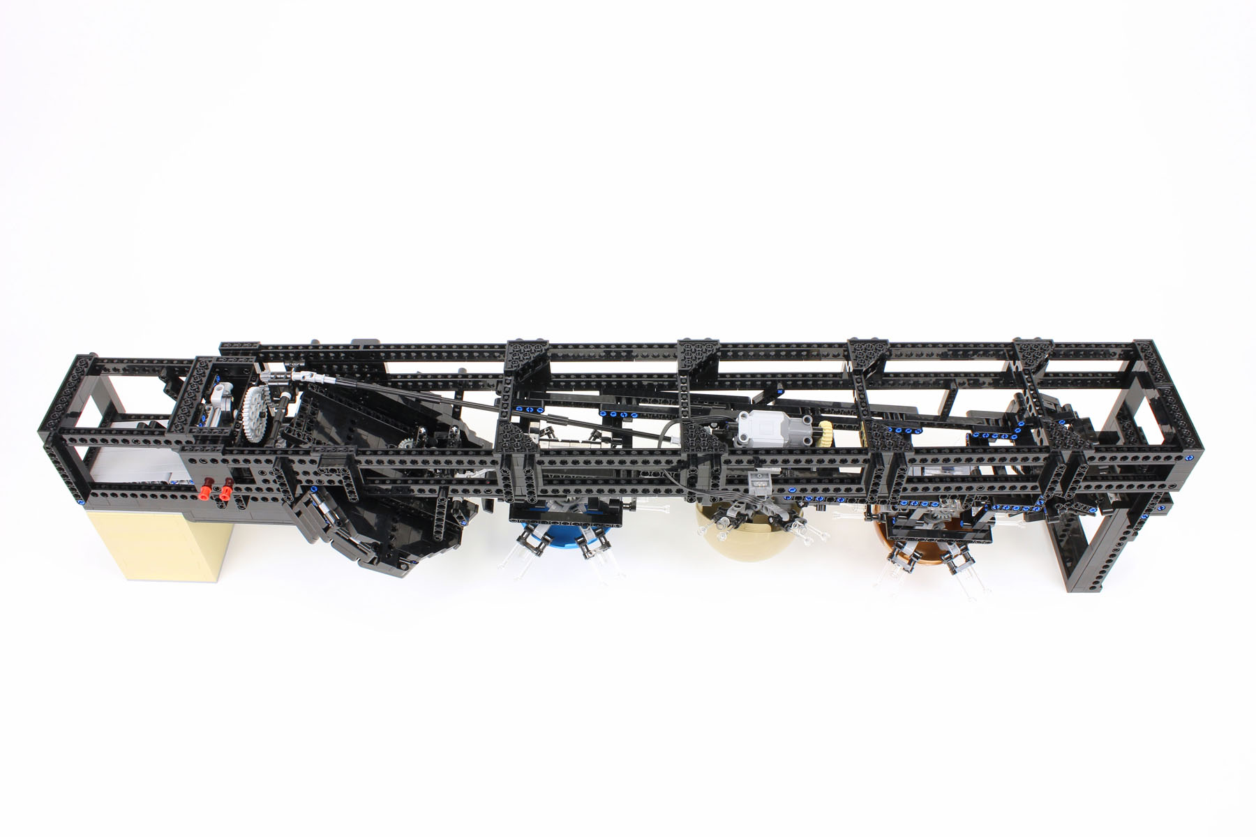
Strain wave gearing consists of three components: a wave generator, a flex spline, and a circular spline. Wave generator, flex spline, and circular spline can be recognized as the light bluish ellipse in the center, the yellow cup, and the dark bluish gray outer ring, respectively, in the GBC module. The number of teeth on the flex spline and circular spline are 32 and 36, respectively. The reduction ratio is calculated using the following formula: Reduction ratio = (circular spline teeth – flex spline teeth)/flex spline teeth = (36 – 32)/32 = 1/8. The wave generator is used as the input, and the flex spline is used as the output. pw160314r1 pw160311r1 
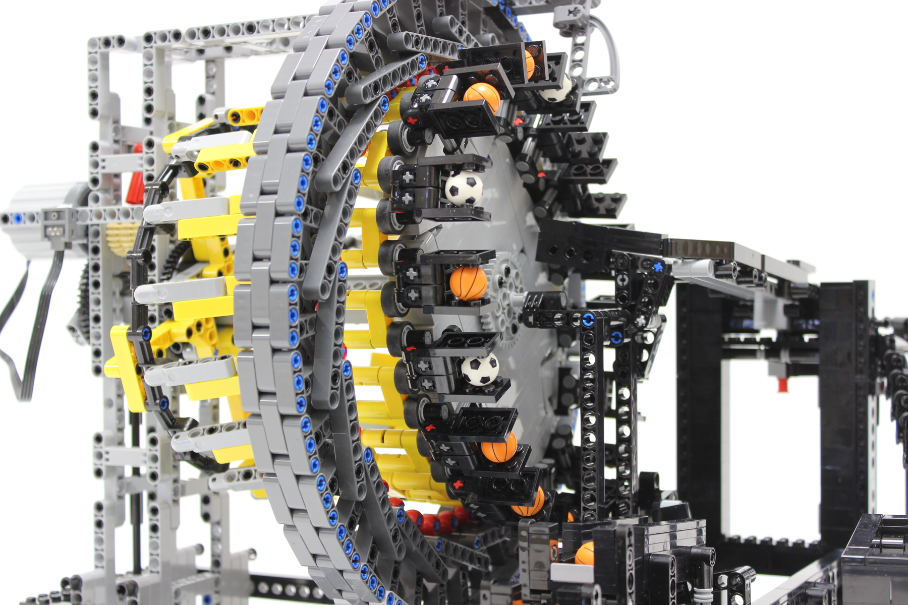
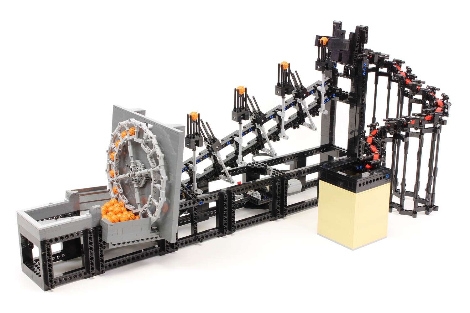
When the mechanism of interest was applied to the GBC module, the desire was for the movement of the balls to resemble that of the mechanism. I used wave motion of the flex spline to transfer the balls in order to use the strain wave gearing mechanism in GBC module. This differs from the actual strain wave gearing that uses only the reduced rotation of the flex spline as the output. 
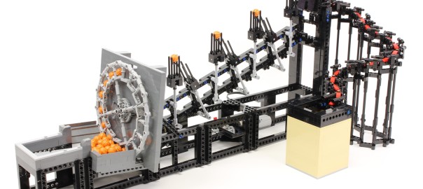
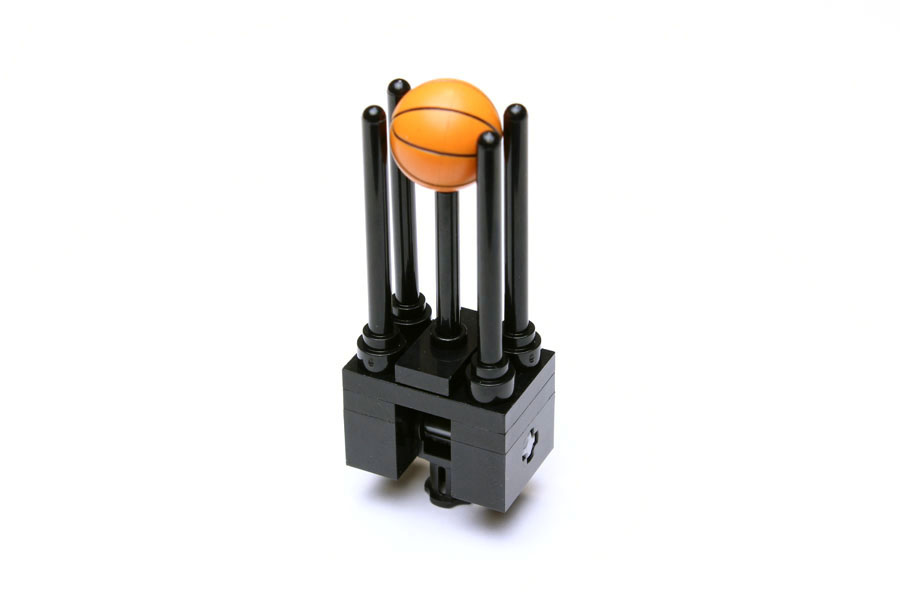
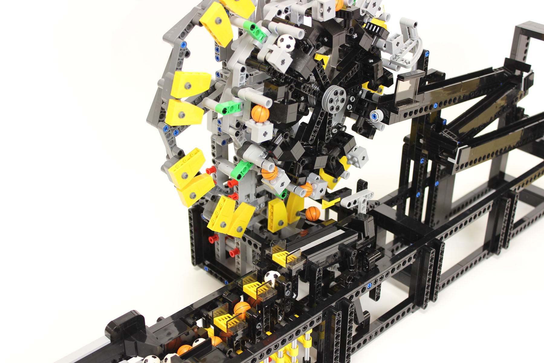
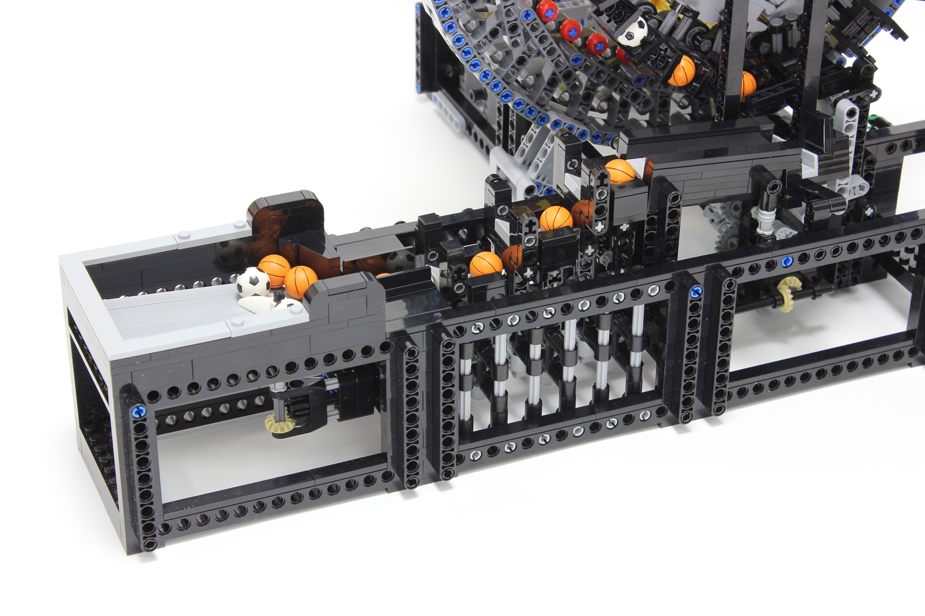
The chucks attached to the front-facing edge of the flex spline are used to grasp the balls. The balls move in tandem with the wave movement of the flex spline, which is the highlight of the module. The distance travelled by the flex spline must be equal to the interval distance (4 studs) of the ball chucks when the wave generator has turned 180°. The four-tooth differential between the flex spline and the circular spline meets this requirement. pw160323r1 pw160324r1 
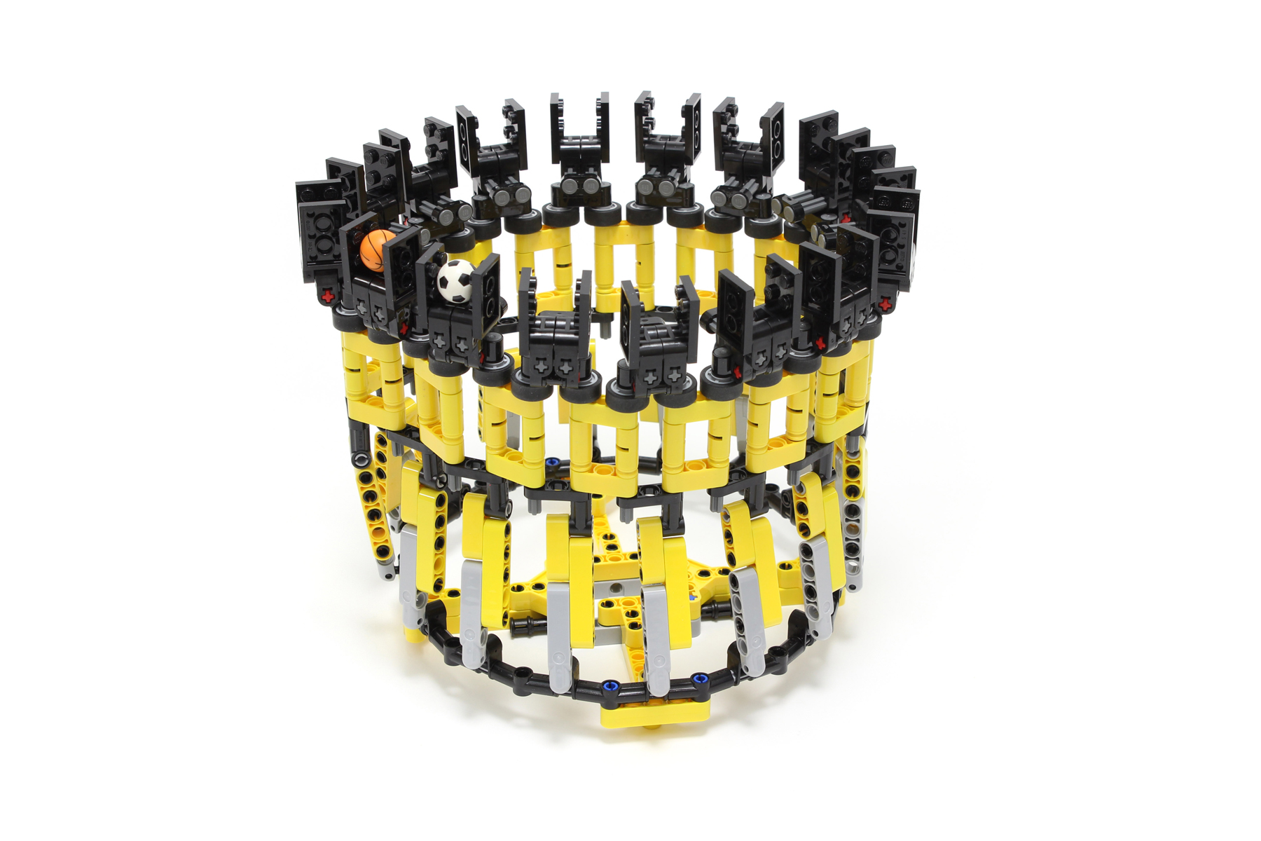
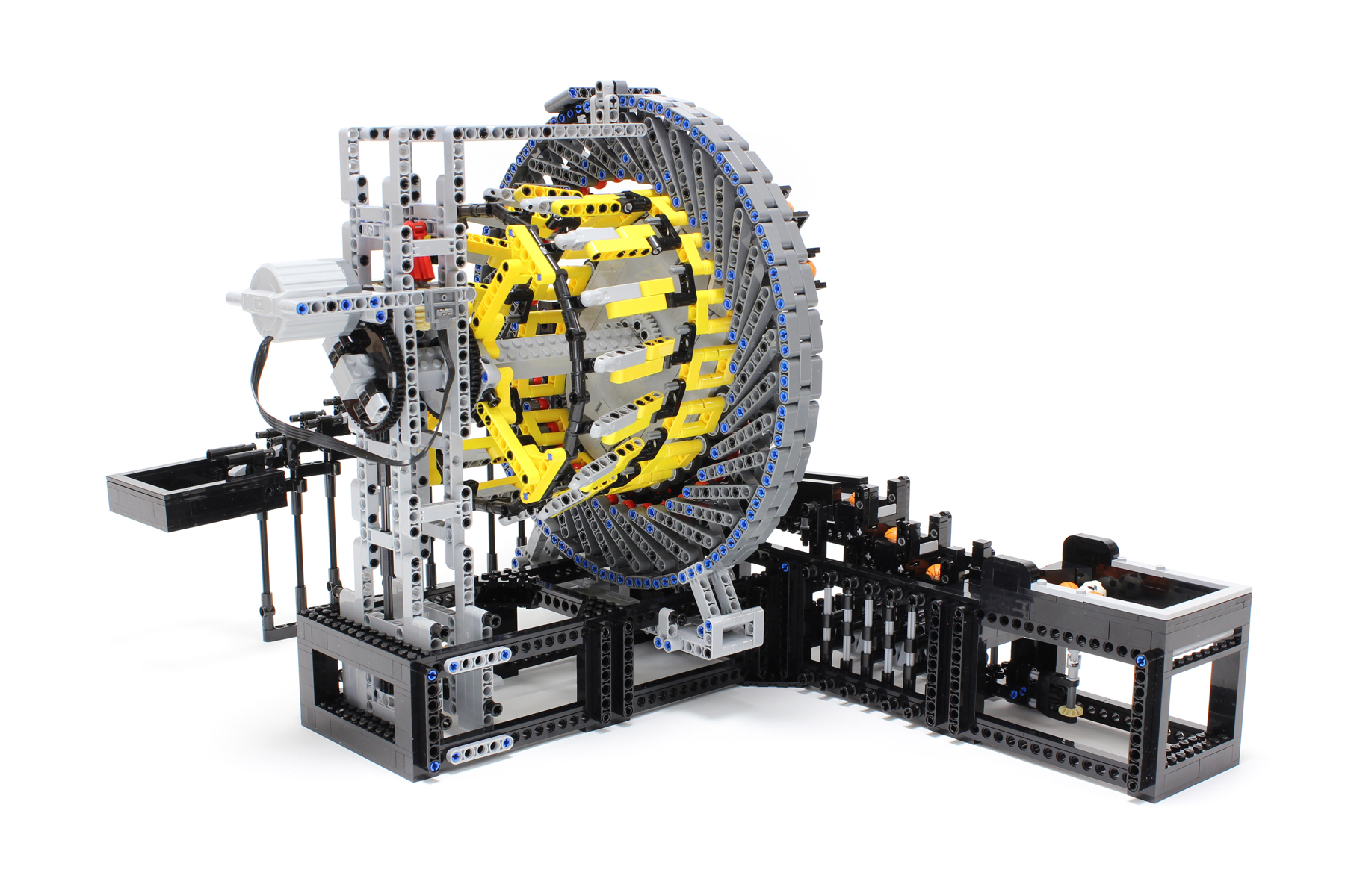
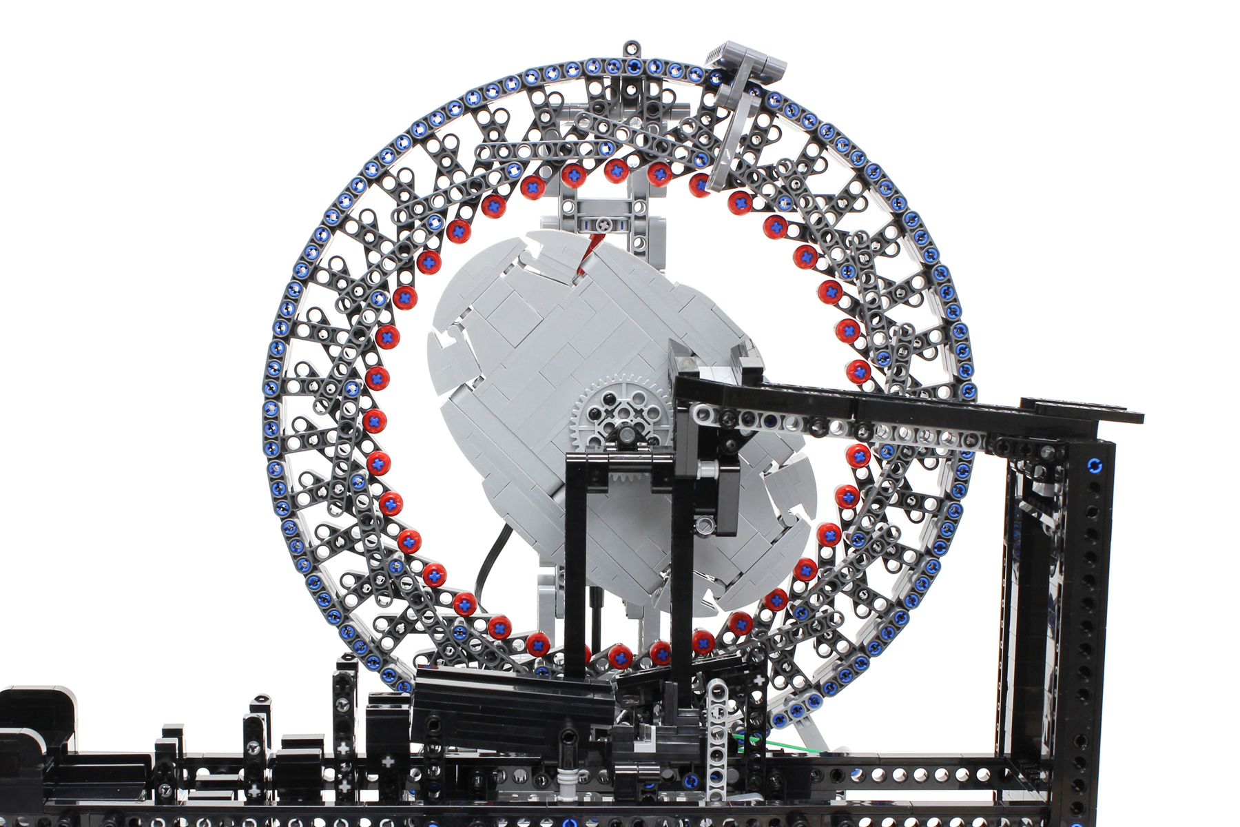
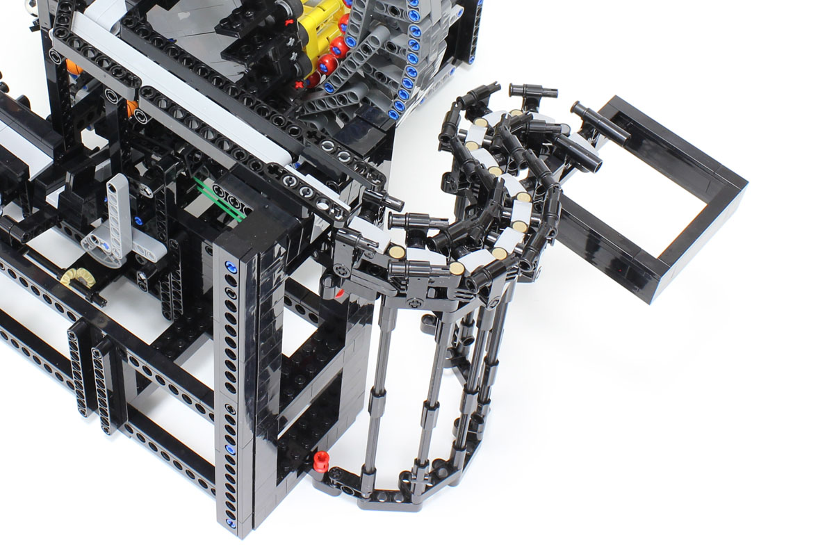
This figure shows the disengaged flex spline. It is necessary for the flex spline to be flexible. The amount of deformation to the flex spline is greater than that of a typical flex spline due to the small reduction ratio of 1/8. The ball joint is used to cope with the large deformation. The deformation capabilities of the Lego assembly allows for a flexible structure. The rollers are attached at the contact point between the flex spline and the wave generator to reduce friction. I focused on making the ball chuck compact. The four-length axle with stop absorbs the deformation of the chuck when grasping a ball. pw160321r1 pw160322r1 
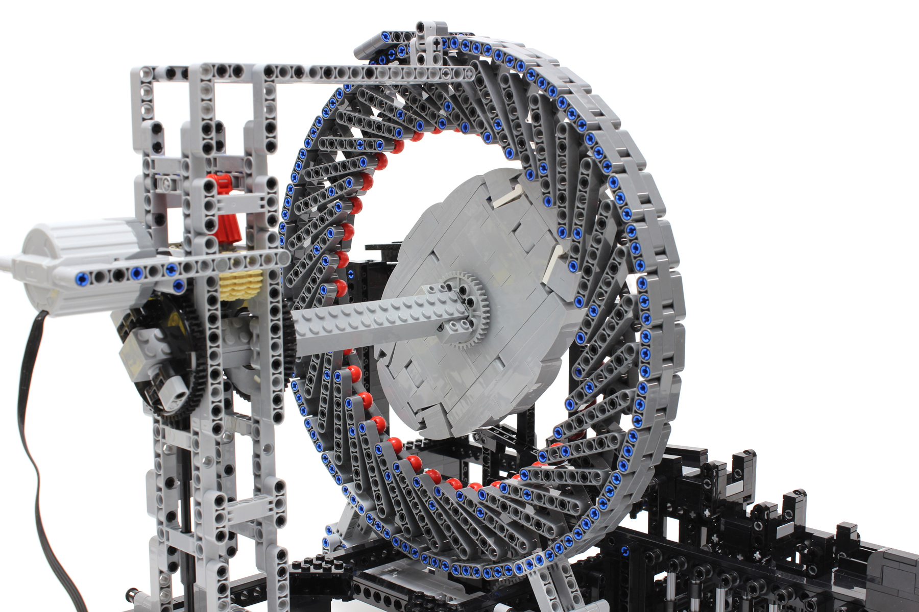
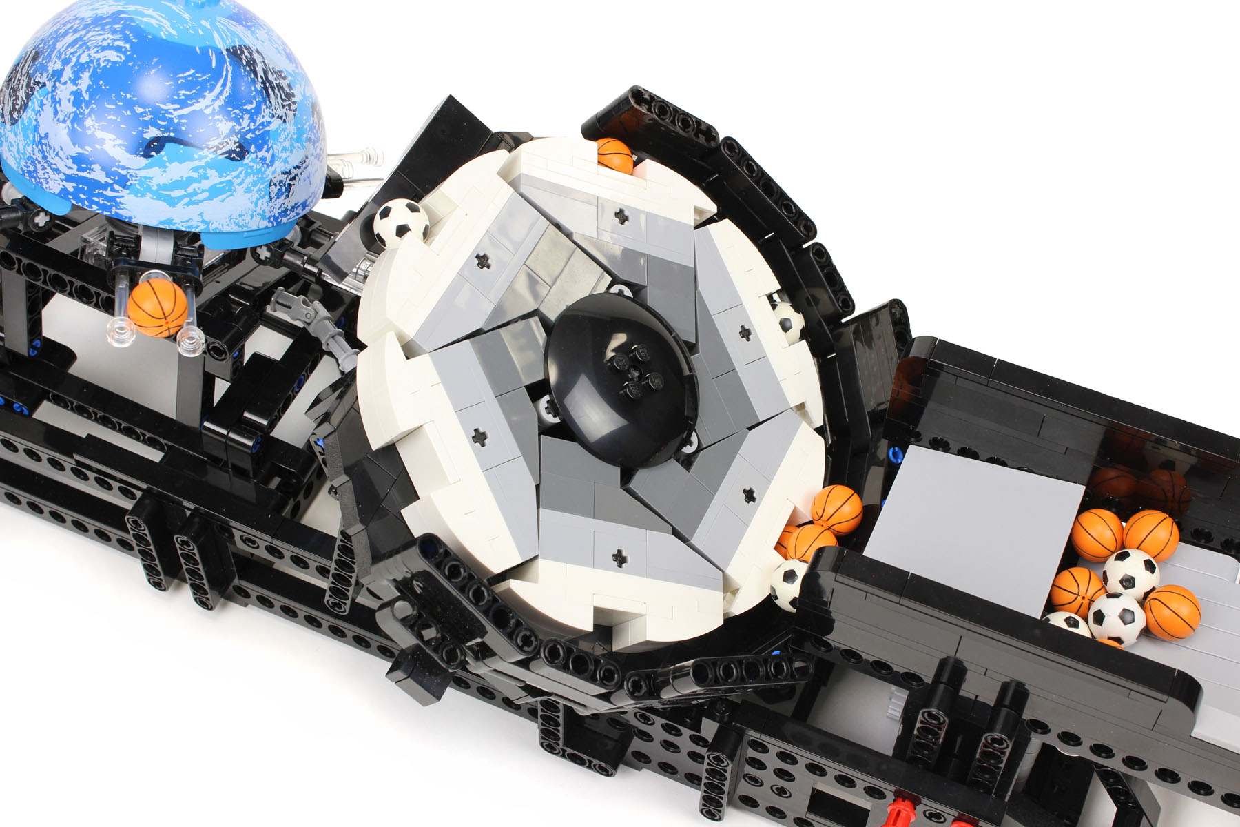
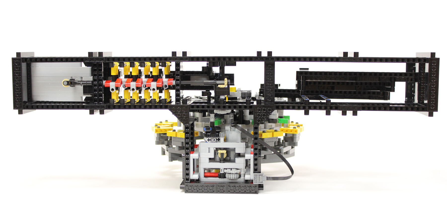
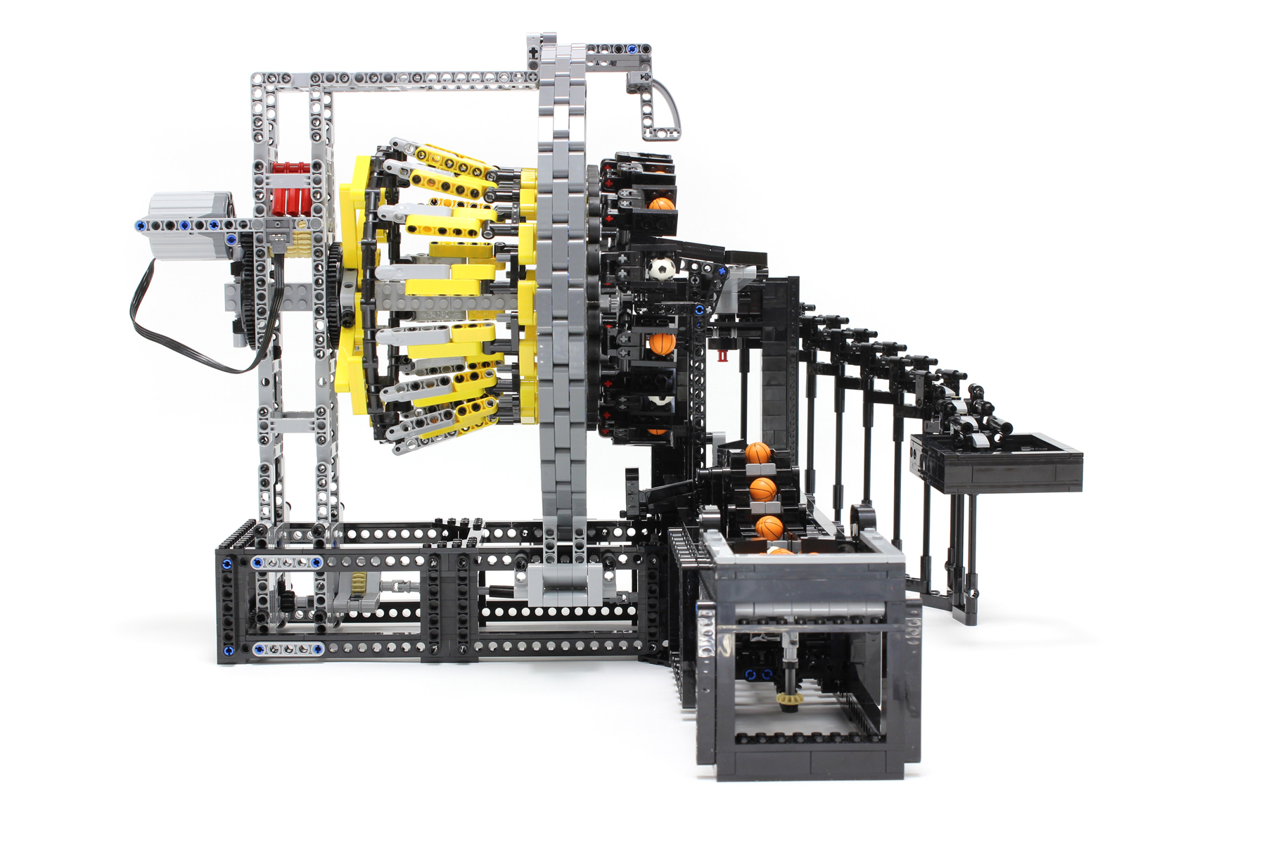
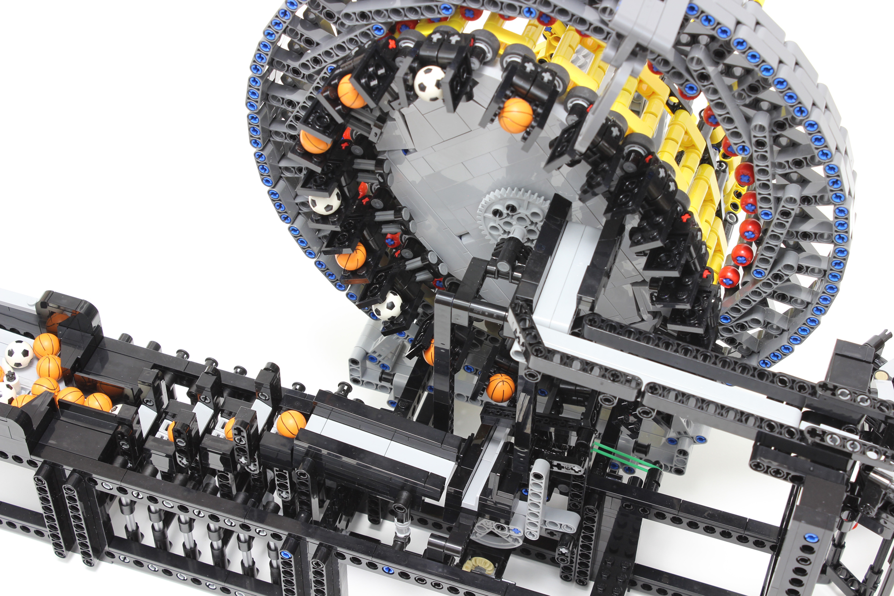
This image shows the strain wave gearing with the flex spline removed, to show the wave generator and the circular spline clearly. The light bluish ellipse in the center is the wave generator, and the dark bluish gray outer ring is the circular spline. The red circular components arranged about the inner perimeter of the circular spline function as teeth. These teeth engage with the teeth of the flex spline. The circular spline proved the most difficult component in this GBC module to design. It was necessary for the circular spline to be a rigid structure, in contrast to the flex spline. The circular spline is subjected to inside-out forces. Many prototypes were produced to achieve the desired geometry of the circular spline having the 36 teeth equidistant from one another, while preserving stiffness and aesthetic appeal. The wave generator is made not using Technic bricks. The ellipse of the wave generator requires accurate adjustment of the major axis length. The major axis length was adjusted to the optimum length using a 1/5 stud. A longer major axis length increases the rotational friction, while a shorter length causes ratcheting. pw160308r1 pw160318r1 
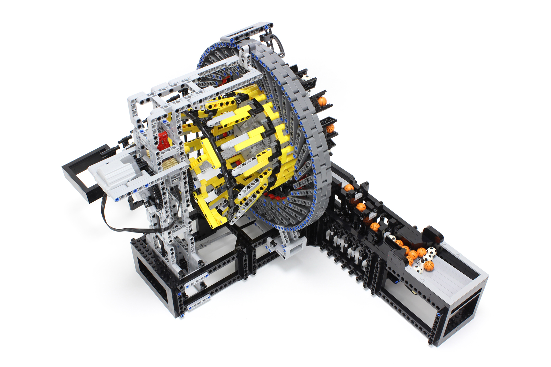
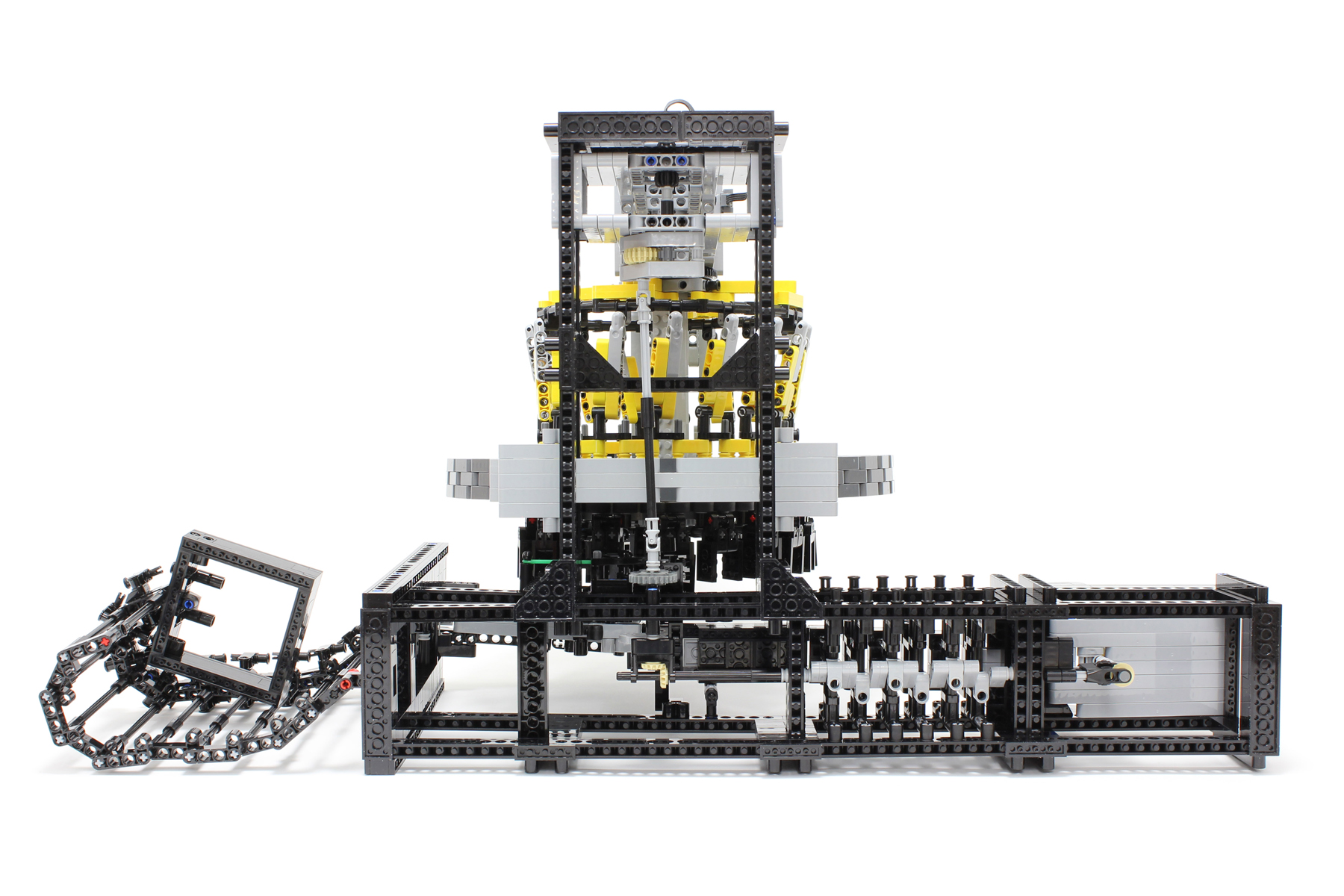
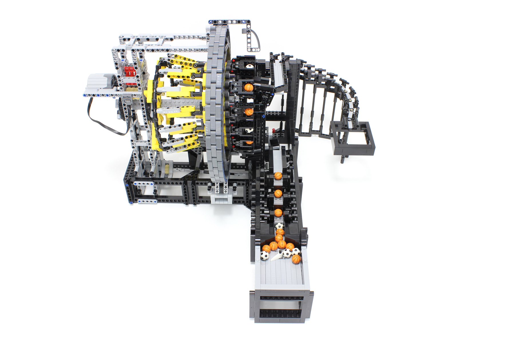
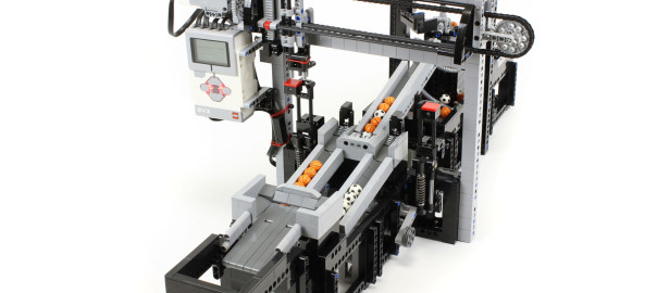
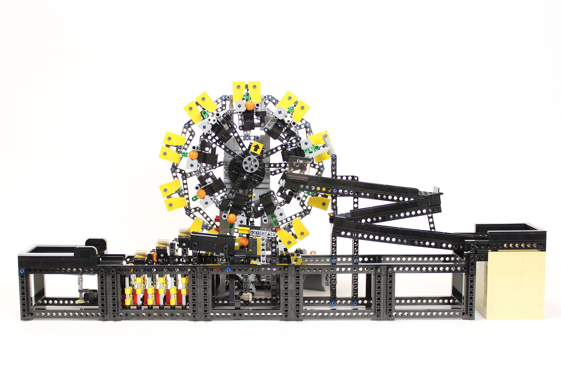
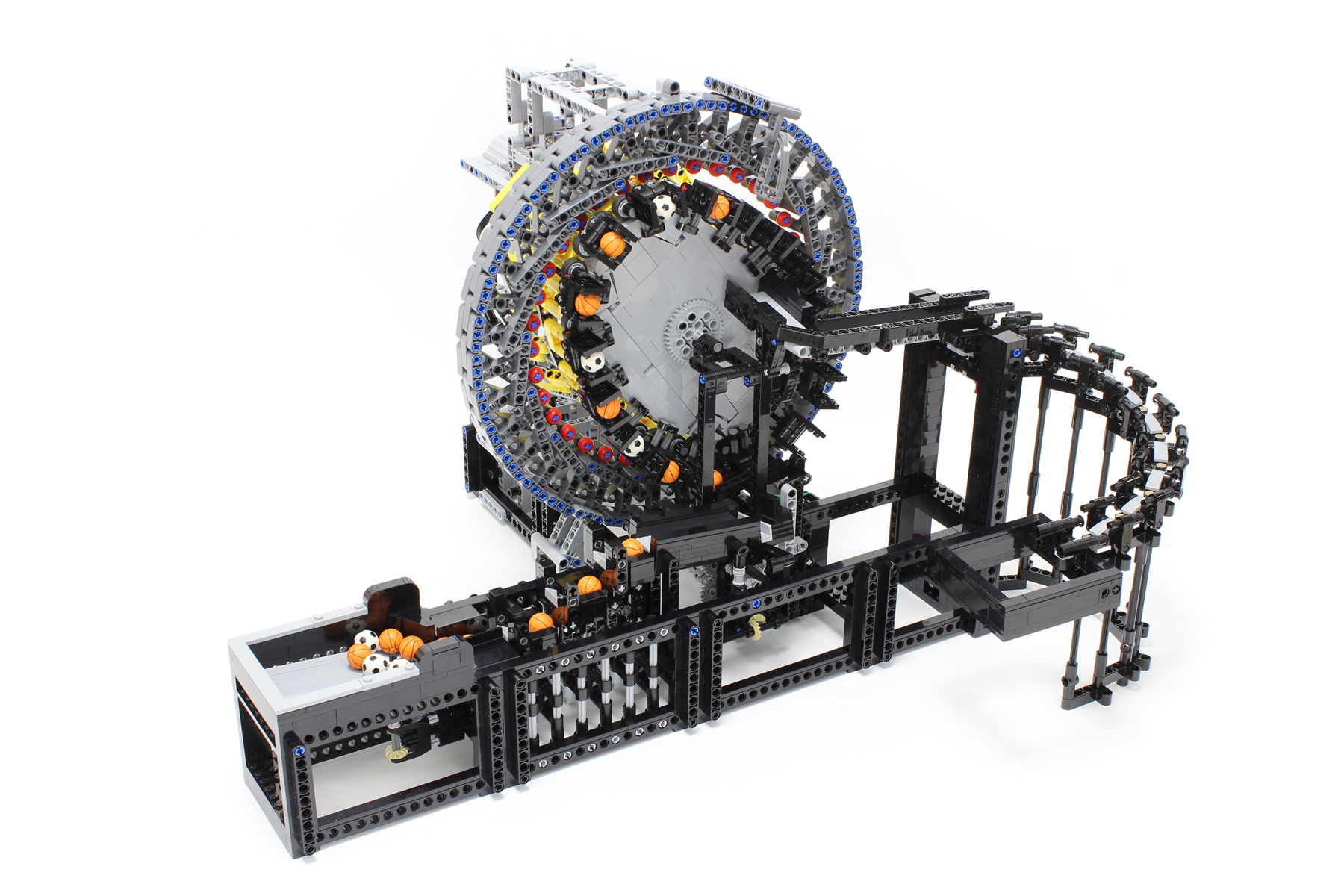
The module has four moving parts: the wave generator, a stopper, a stepper, and an agitator. The stopper is located at the entrance of the wave strain gearing and determines the timing of the ball entry. All moving parts of the module are driven by a single PF XL motor. There is no torque limiter between the motor and the load to secure power transmission. pw160310r1 pw160325r1 
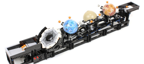
The stepper part of the module is the same design as that of the cycloidal drive GBC module. The slide part of the module is the same design as that of the Fork to Fork GBC module. The durability of the module has not yet been tested. It is envisaged that the durability of the module will be poor owing to the heavy load on the strain wave gearing. pw160320r1 pw160306r1pw160302r1 pw160305r1pw160309r1 pw160304r1pw160313r1 pw160319r1  

Planets GBC module

Started: October 2015 Completed: March 2016 Released: April 2016
pw160101pw160107 The 3rd GBC module using antenna parts (ID 3957). Hemisphere parts with planets pattern of Star Wars Series are used as decoration. A prototype of the module had no decoration of planets. Fortunately, I happened to find the hemisphere parts at my working table which were kept for another purpose, and I could attached them. The module represents that the balls go around each planet and move to the next planet as if a spacecraft traveled around planets in a solar system. pw160102pw160103 The mechanism of the Planets GBC module is simple that five rotors rotate continuously. The axis of rotation of five rotors are tilted to each other, which enables the balls to move to the next rotors. Strict adjustments of phases of five rotors are necessary for passing balls smoothly. I try to make a structure that enables fine adjustments of a phase of each rotor. The module works well once adjusted. The module consisted of two divided blocks, which goes in a usual transporting container (73 cm in length). pw160104pw160105 I had difficulty to improve a discharged part, especially the shape of comb tooth of a triangle rotor. pw160106 One PF-L motor drives the module.

Fork to Fork & Snake Slide GBC module

Started: October 2015 Completed: October 2015 Released: October 2015
The 2nd GBC module using antenna parts (ID 3957). Antenna parts are used for the tip ends of the forks. The circular motion of the forks deliver the balls one by one. pw050101 pw050103 On each fork, four antenna parts are attached into a square. The balls are captured by the four antennas. Arrangement of the four antenna parts is not a regular square but a rectangular. Forks with a regular square arrangement would not be able to deliver the balls. Since the adjacent two forks are arranged alternately with 90 degrees difference, the tip ends of the two forks do not hit and slip through, and they deliver the balls successfully. bIMG_1670-1bIMG_1685 The mechanism of lifting up the balls with forks in this module requires own vertical thickness. Consequently, only the ball delivery mechanism with forks could not be completed as a GBC module. The higher access point of the module which receives the balls first would not be able to satisfy standards for a GBC module. Inserting a rotating wheel between the access point of the module and the mechanism transferring the balls with forks could actuate it as a GBC module and satisfy the standard. The rotating wheel also acts as a buffer and a ball feeder to the forks at regular intervals. The rotating wheel is the same design that I designed in 2009. The method of lifting up the balls by the rotating wheel is not my idea. The mechanism of this module is simple and stable. A flexible slide was adopted for a discharge part of the module. The flexible slide will be one of my favorites. It is cute and also practical for the connection to the next GBC module, for example.  

Fast Ball Sorting Robot using EV3

Started: June 2015 Completed: August 2015 Released: August 2015
This great ball contraption (GBC) module is capable of sorting two types of balls. The two-axis gantry robot placed at the center of the module sorts basketballs and soccer balls in a pick-and-place motion. The motion of the two-axis gantry robot is quick, and the sorting speed of the robot is greater than two balls per second. The module is controlled by Mindstorms EV3. The basketballs and soccer balls are distinguished using an EV3 color sensor embedded below the guide lane for running balls. pw150401pw150402 pw150403pw150404 I attempted to develop a two-axis gantry robot that moves faster. The weight of the moving part must be low in order to make the robot move fast. The weight of the motors prevents fast movement; thus, the motors were attached to the fixed part instead of the moving part, thereby achieving a lighter handling part in the developed model. The improved structure was obtained using a 32L long axle and a sliding red 8-tooth gear. The ball-handling robot moved faster than I expected. The speed of the ball feeding mechanism, where the balls are lifted up one by one, was lower than that of the ball-handling robot in the prototype. pw150405 The robot was actuated by two EV3 medium-sized servo motors. Although I wanted to use a large-sized servo motor with more power in order to make the robot move faster, I used medium-sized servo motors because the inner gear backlash of a large-sized motor is larger than that of a small-sized motor. In addition, the rotation speed of a large-sized motor is too low for use in the module. The program, which was executed in an EV3 brick, was written in Lego Mindstorms EV3 language. The number of basketballs and soccer balls was counted using the information from the color sensor. Whenever the ball storage lanes were filled with the distinguished balls, the EV3 brick gave the command to discharge the balls. The robot pushed the switch to discharge the stored balls; thus, both the ball sorting and discharging functions were performed by one robot. An interesting aspect of this module is the contrast between the fast sorting and slow discharging motions.

Cycloidal drive GBC module

Started: April 2015 Completed: June 2015 Released: June 2015
  This great ball contraption (GBC) module was developed with an idea by the mechanism of a cycloidal speed reducer. The movement of a cycloidal disk in the reducer was applied to the ball carrying mechanism of the module. It is difficult to accurately reconstruct the reducer with Lego bricks; thus, the reducer part of the GBC module was modified from the actual one. Although the role of a cycloidal disk was represented by the pinwheel in the module, the actual reducer disk has a smooth and peculiar-shaped circumference. As a result, the pinwheel was engaged with an outer wheel (ring gear) at only one contact point. Strictly speaking, the module did not resemble the cycloidal speed reducer. However, I think that the module does resemble the gear motion of the reducer. pw150301pw150304 pw150303pw150302 The peculiar movement of the reducer was effectively used for catching and releasing the balls in the module. The arrows at the rotation center indicate the position where the inner and the outer gears are engaged. The GBC module consisted of ball carrying mechanisms driven by the reducer and stairs with six steps. The stairs acted as a buffer and a ball feeder to the wheel at regular intervals. The ball carrying system of this module was stable. Techniques to make regular polygons with high precision are necessary to actually operate the ring gear and the cycloidal disk. However, it is difficult to make regular polygons with Lego bricks. Liftarm parts assembled in triangles can provide various angles. Using this technique, nine- and ten-sided regular polygons were assembled for the module. I attempted to make them with sufficient stiffness. The number of teeth of the cycloidal disk and ring gear were nine and ten, respectively, and they were selected by considering the difficulty to make the polygons with Lego bricks. pw150305
  • Page 3 / 3
  • 1
  • 2
  • 3