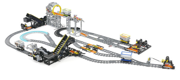
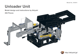
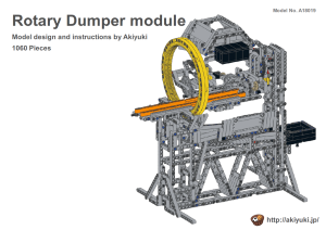
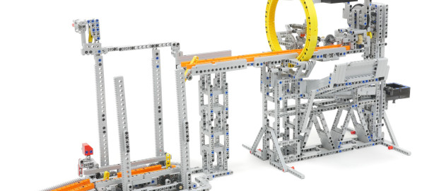
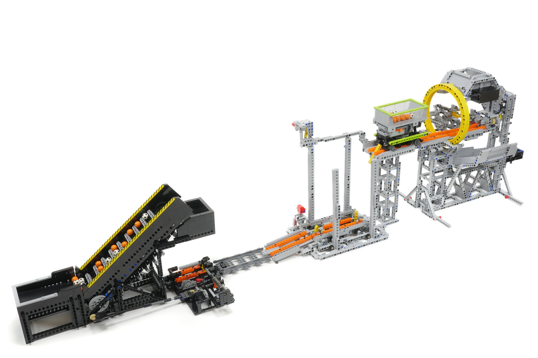
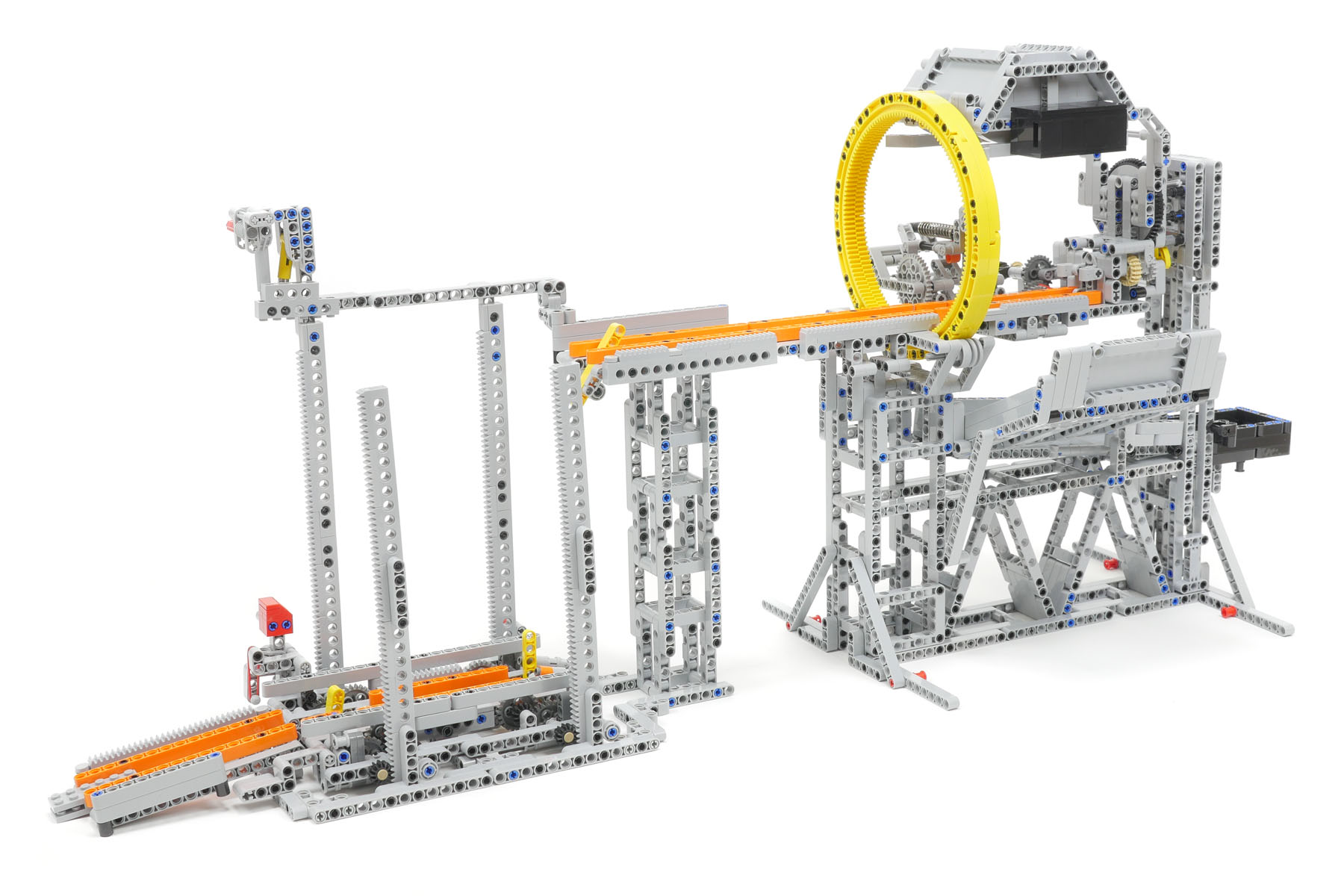
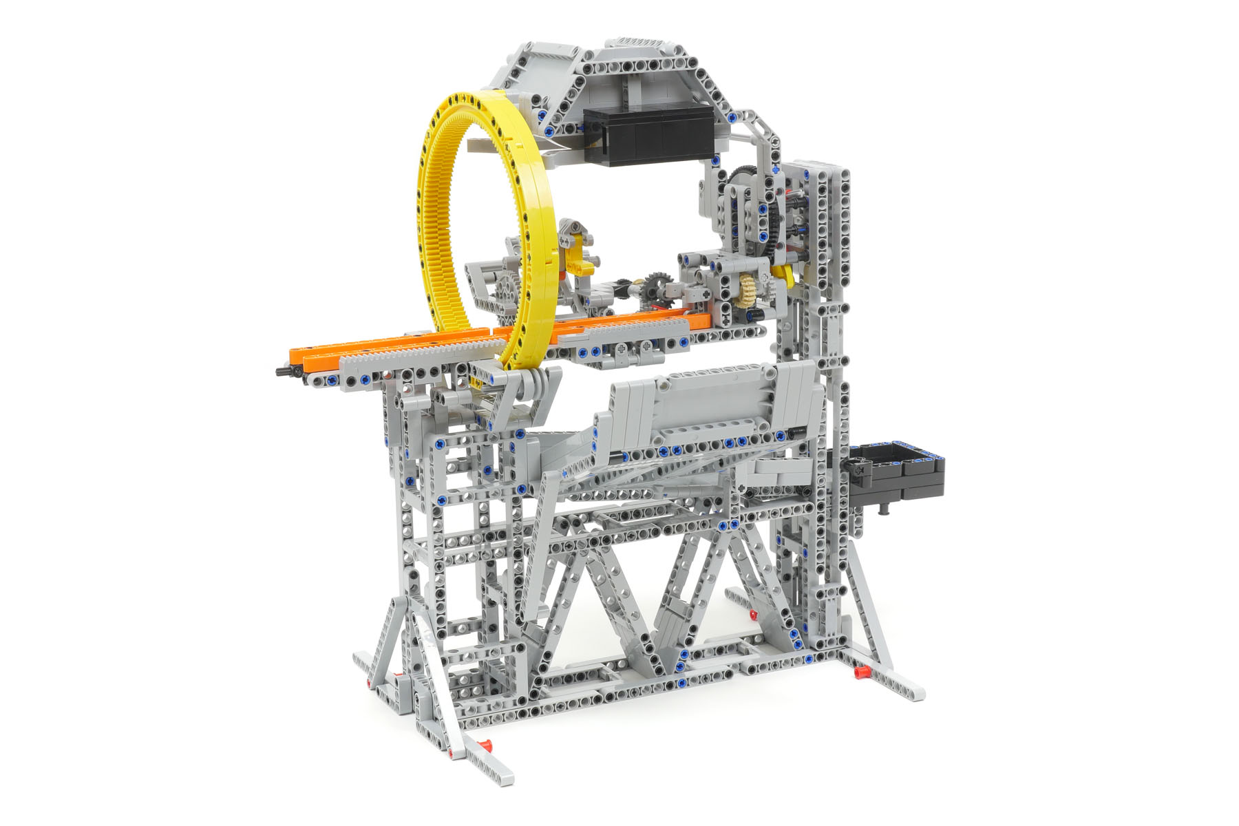
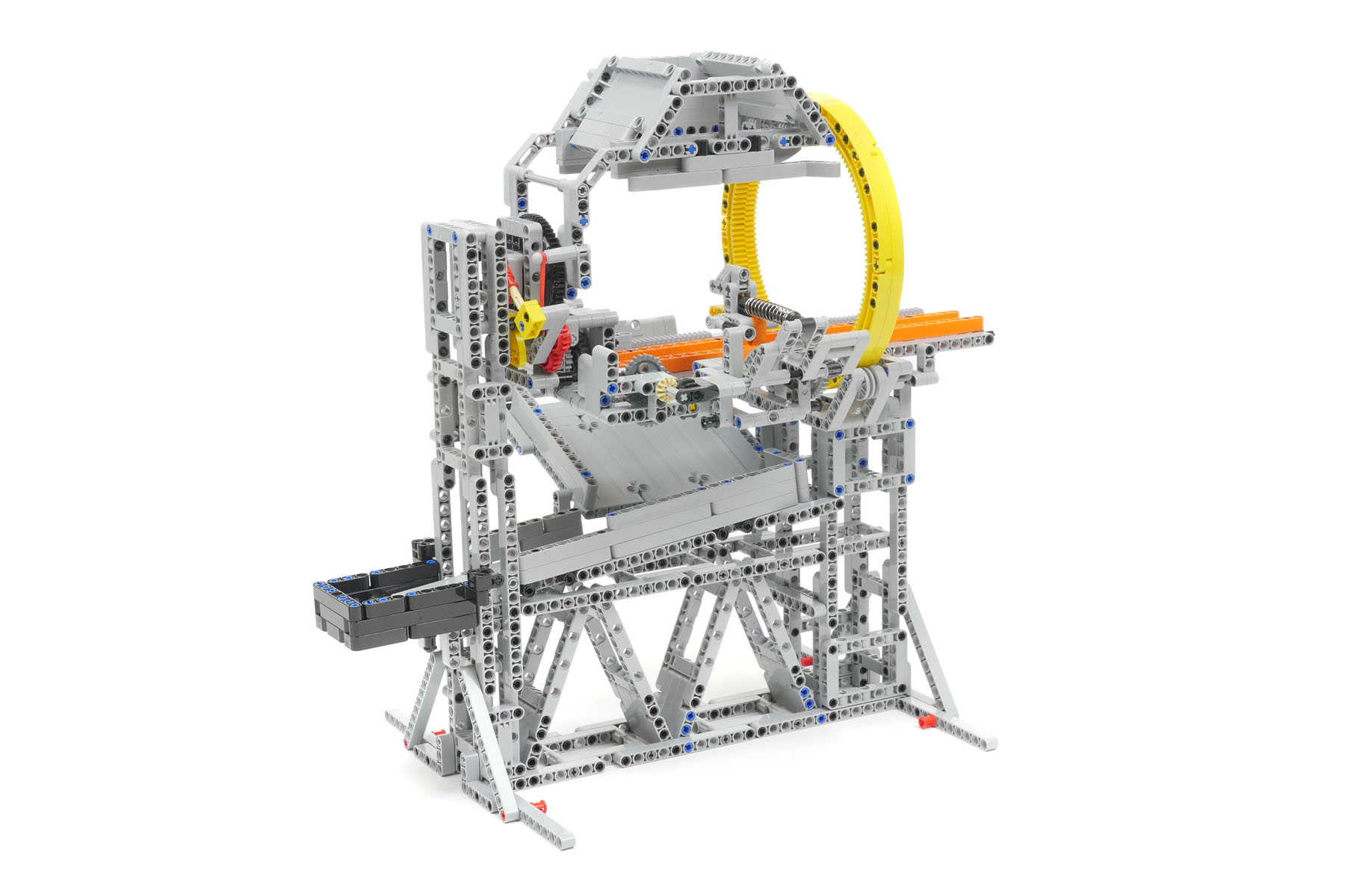
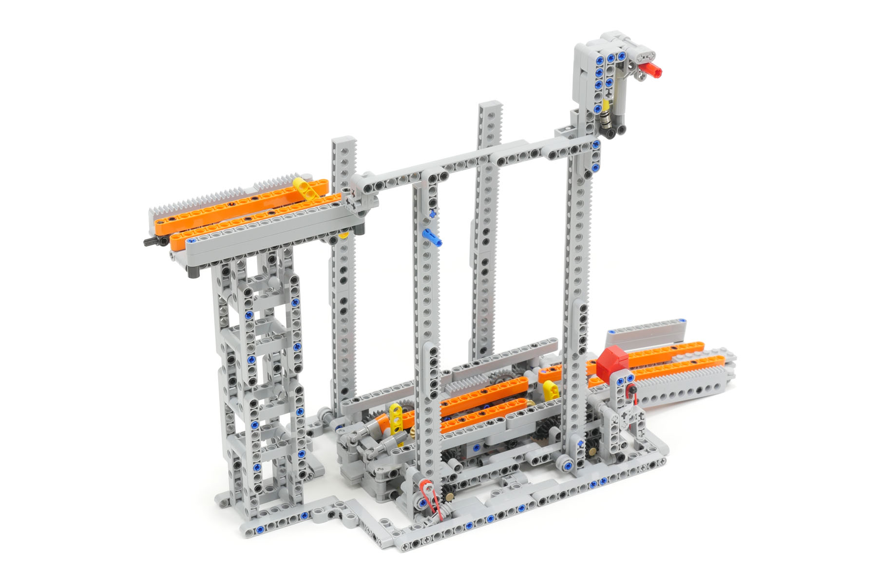
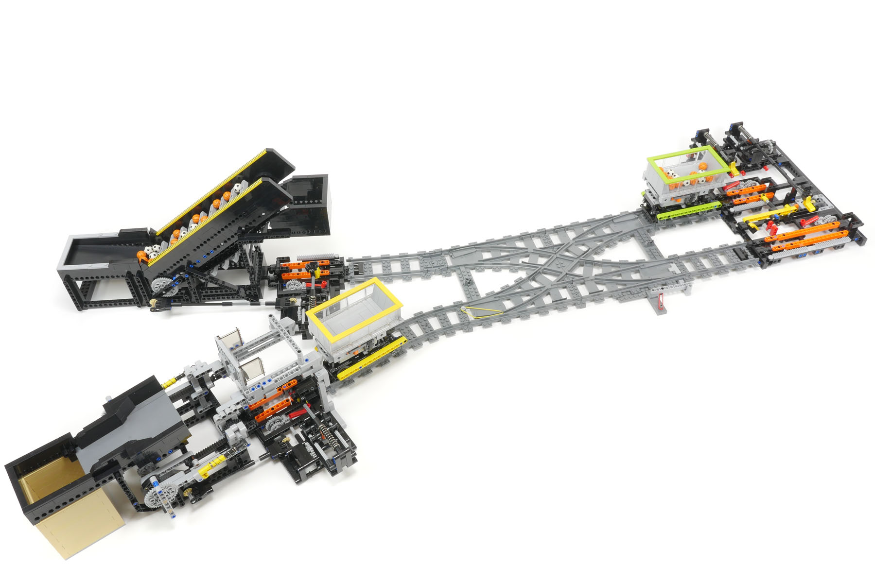
I introduce the Rotary dumper module that is a specific type of Unloader module. The container on the train that enters and stays in the module is rotated along with the train itself in order to unload the balls from the container. The Rotary dumper module can be operated in combination with the Elevator module that lifts up and down the train because a given height of the train is necessary to operate the Rotary dumper module. A sample layout using the Rotary dumper module and the Elevator module is shown below.
Rotary dumper module
After the train arrives and stays in the module, the track and cylinder that surrounds the train all rotates with the train. During rotation, the balls in the container on the train are unloaded. After rotation, the train starts to leave the module in the reverse direction. The movement of the module is controlled by the motor on the train. The height of the lane to unload the balls is justified to that of the GBC (Great Ball Contraption) standards between the GBC modules so that the module can be connected to the GBC modules.
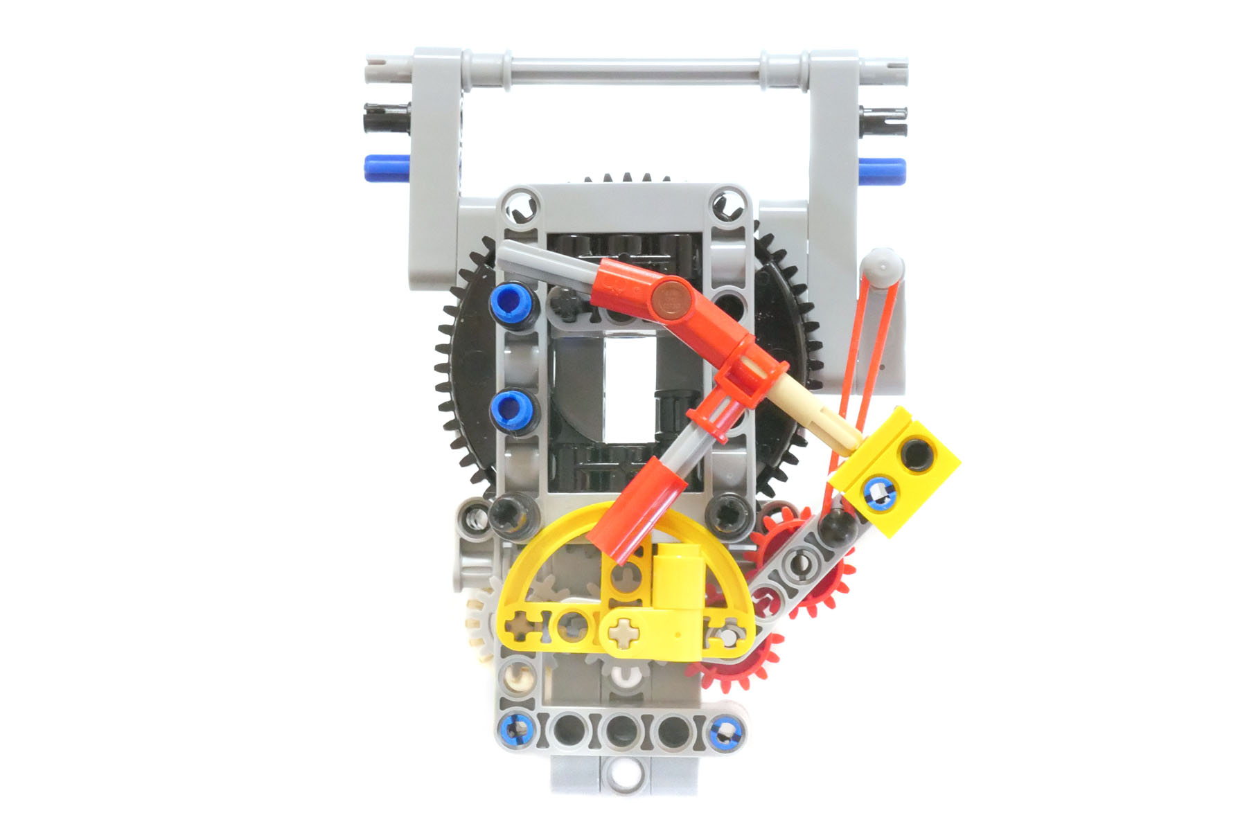
The cam-lock mechanism is adopted in the Rotary dumper module. After the rotation of the track and cylinder surrounding the train, the position of the train should be exactly horizontal. If not, the train cannot move into the Elevator module. After rotation, a semicircular-shaped yellow cam is placed between the two pins, which fixies the track and cylinder in the horizontal position for a certain period of time. Then, the train should be started while the cam-lock is still effective. The timing of the trigger that controls the starting of the train must be adjusted precisely.
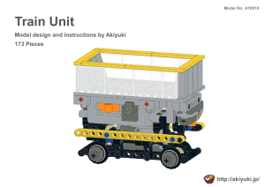
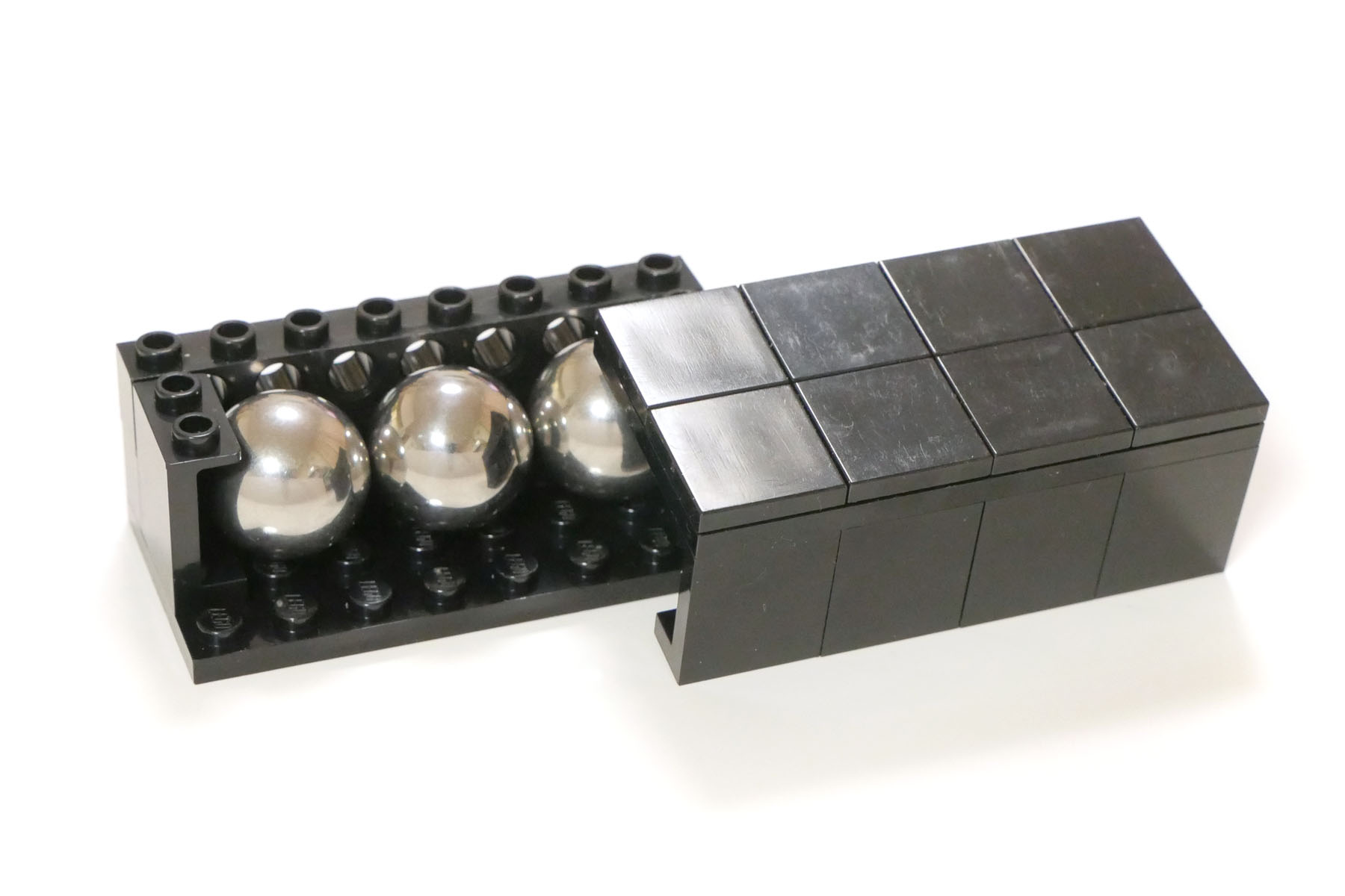
The black box located at the upper part of the module is a balance weight. The weight is 95g and three steel balls 18mm in diameter can be found inside the box.
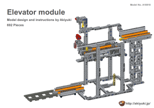
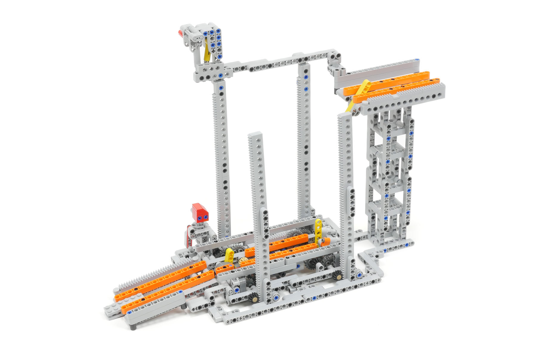
Elevator module
This module performs the function of lifting up the train to the right height to enter the Rotary dumper module. The up and down movement of the Elevator module is controlled by the motor on the train. I spent a lot of time trying to speed up the movement. I first used worm gears to operate the up and down movement. The friction of the worm gears, however, was too large to increase the up and down speed. Then, I developed a gear mechanism that consists of a rack and pinion gear and a reduction spur gear. This attempt to speed up the elevator module is the biggest struggle I faced in developing the railway system. I installed a safety function to prevent the train from falling off the upper track when the track of the elevator module is at the lower position. The yellow-colored parts in the upper track act as a stopper if the train moves ahead on the track at the lower position.
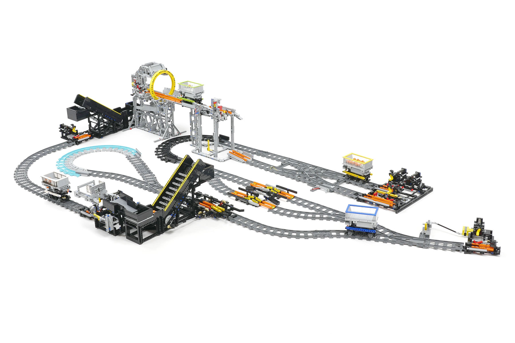
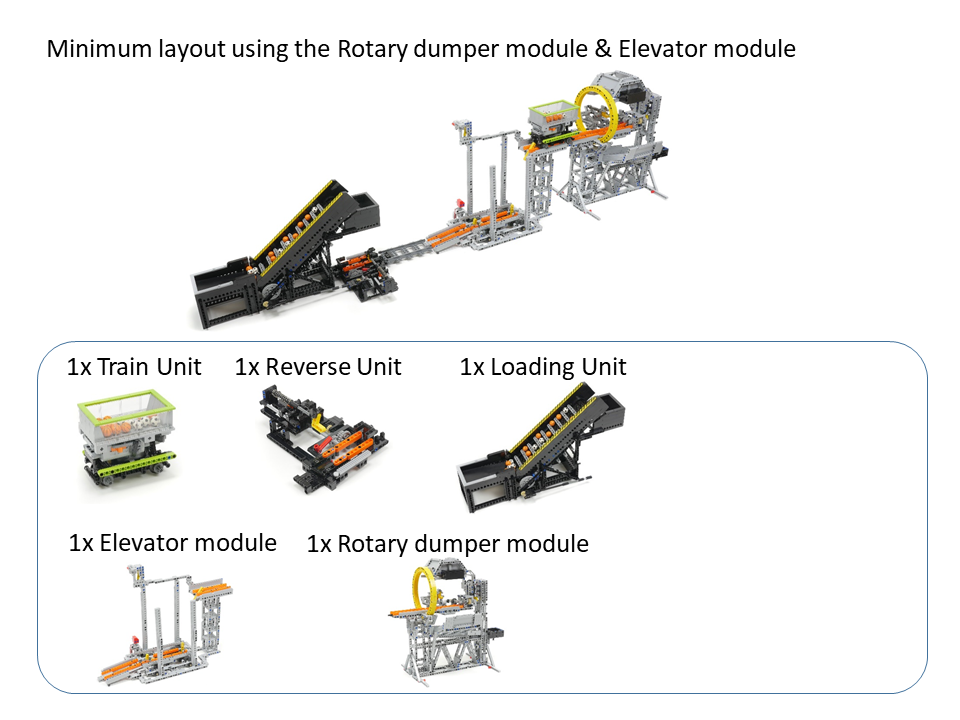
Components of the minimum layout using the Rotary dumper module & Elevator module:
Instructions and MPD files for the components of the minimum layout using the Rotary Dumper module and the Elevator module:
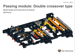
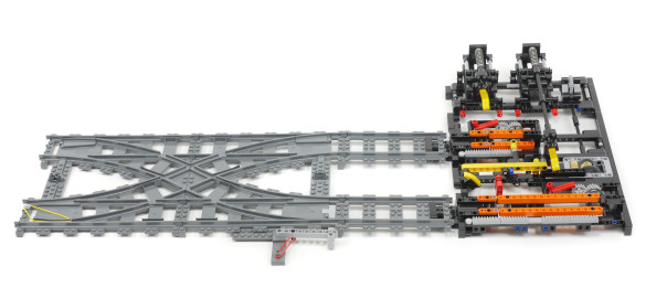
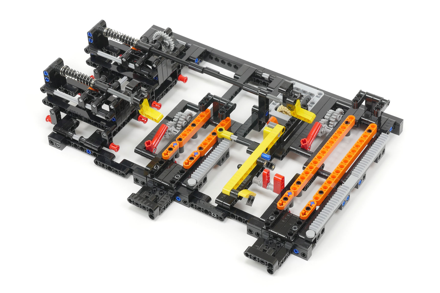
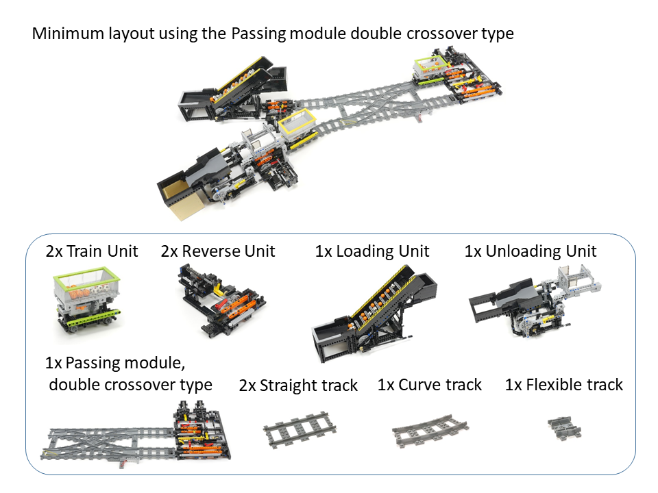
This module has a function that enables two trains to return and pass each other using a double crossover track. This module functions with at least two trains.
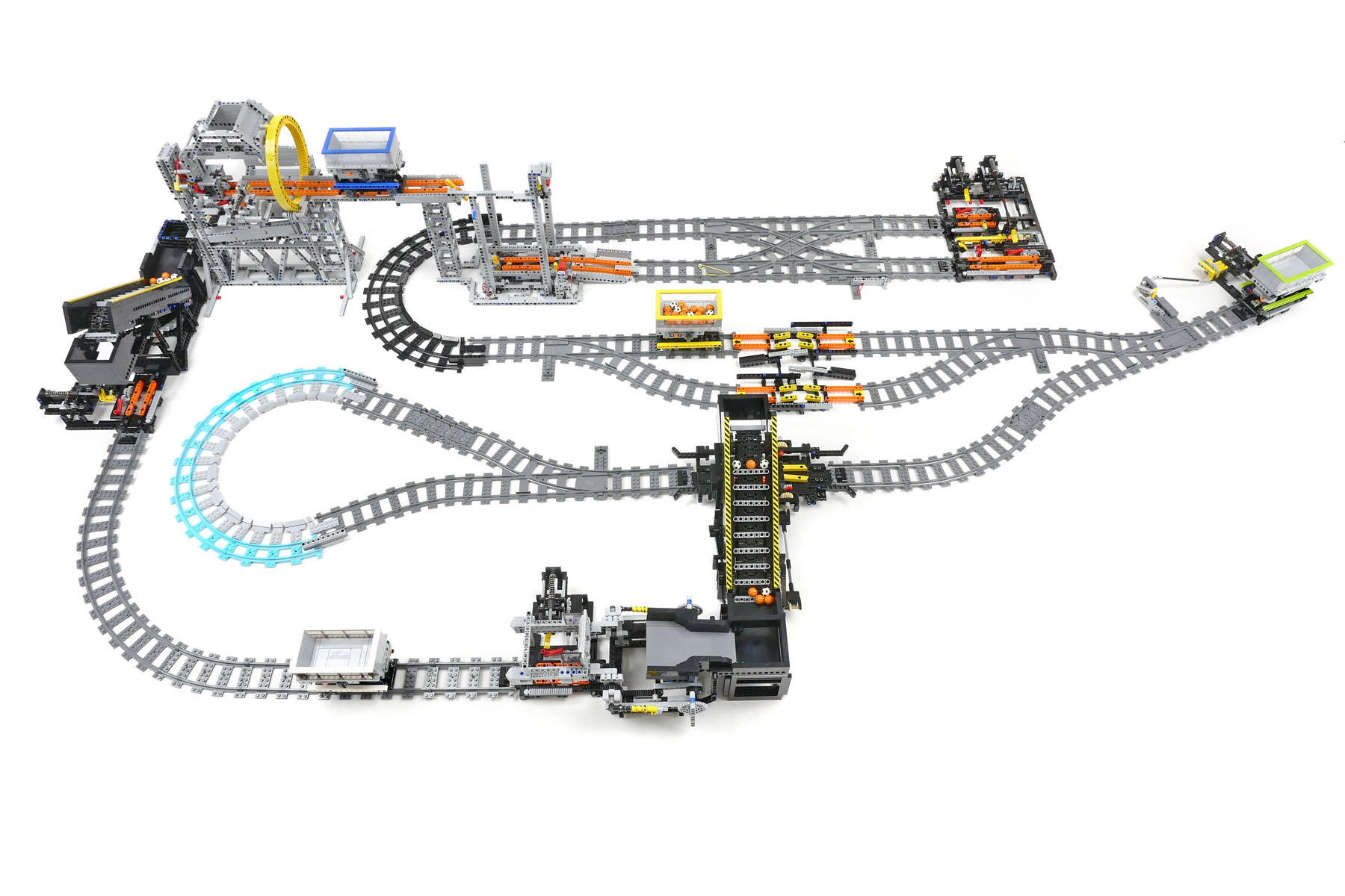
The following photograph shows the minimum layout in which the module operates.
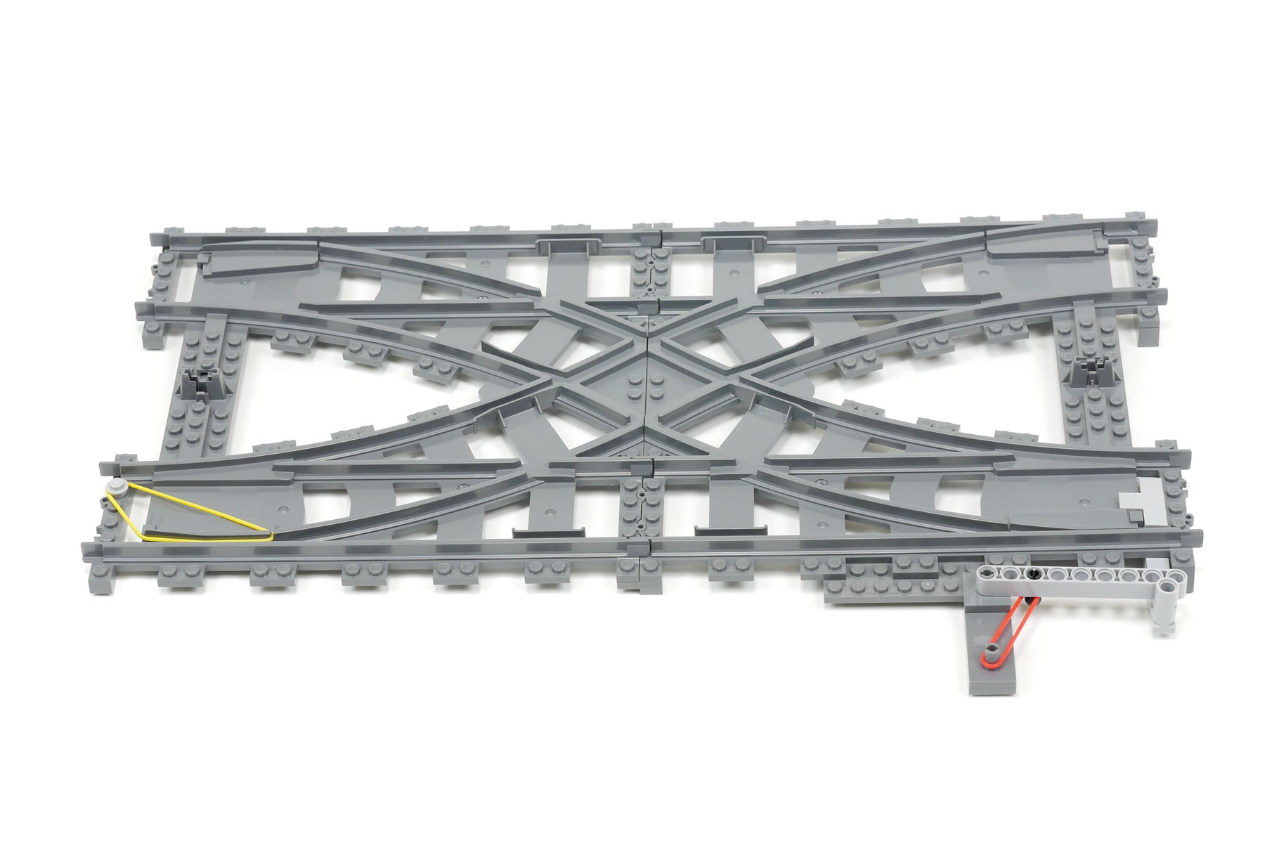
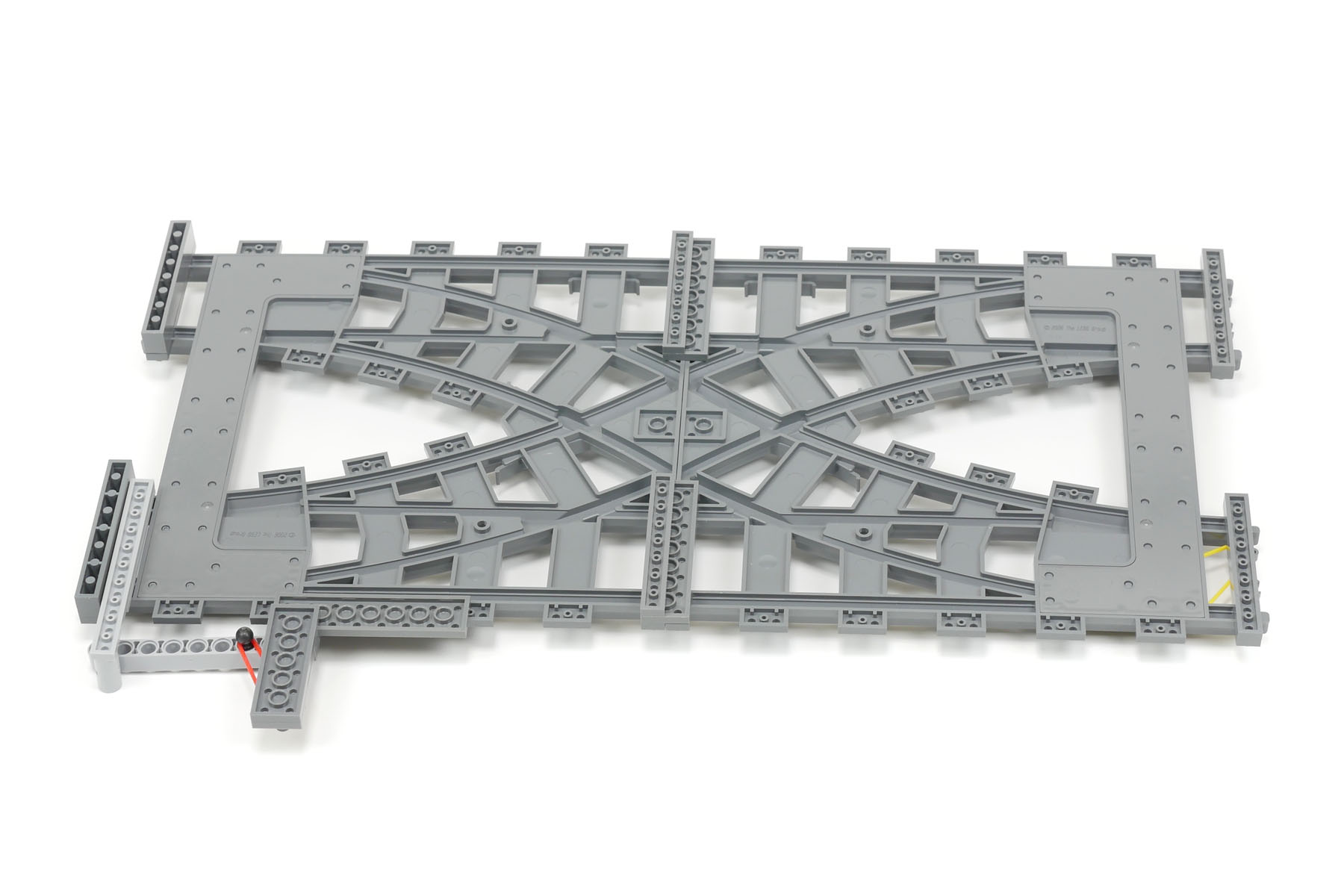
This module consists of a double crossover track and the reverse part. The position of two tongue rails of the double crossover track must be fixed with two rubber bands to operate the module. Please refer to the following photographs and find the yellow and red rubber bands. I have prepared the instructions for the reverse part of the module (see end of this page).
Here, I explain the operating sequences of the module. First, the train runs straight to the module and stays there until the second train on another parallel track enters and stays at the module. Then, the first train starts and runs diagonally on the double crossover track. After the first train runs through the crossover track, the second train runs diagonally on the crossover track. As a result, two trains changed directions and tracks.
Unfortunately, the double crossover track is difficult to find and is traded at a high price (at present, March 2018). Therefore, the module is difficult to build.
Components of the minimum layout using the Passing module double crossover type:
Instructions and MPD files for the components of the minimum layout using the Passing module double crossover type:
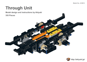
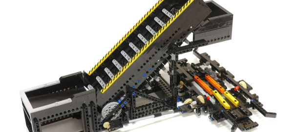
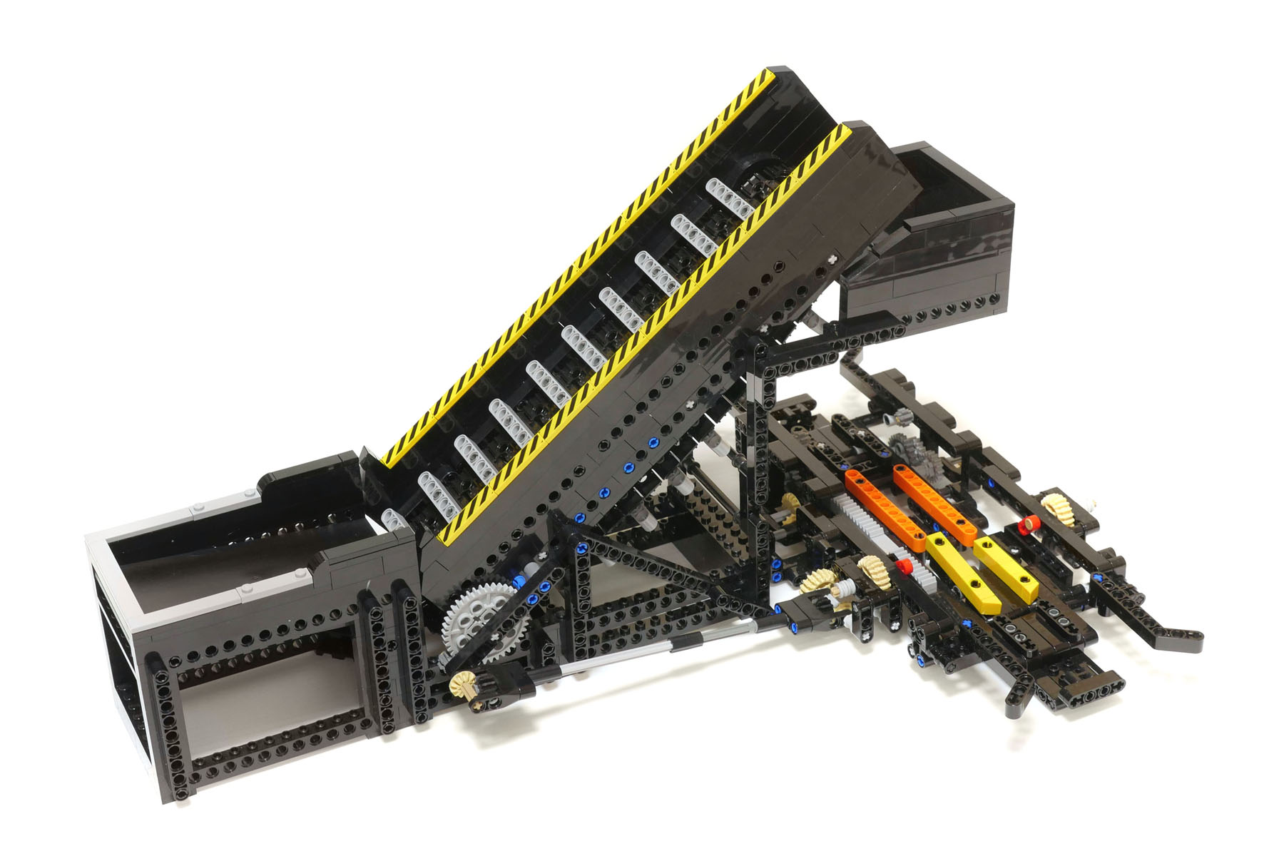
This module consists of two components, a Through Unit and a Loader Unit. A train enters and stays at the Through Unit. Then, the electric motor on the train drives the Loader Unit attached to the Through Unit. After the Loader Unit has finished loading the balls into the container on the train, the train leaves the Through Unit. In this way, the Through Unit enables a train to stay on the track for a while and to drive some component attached to the Through Unit.
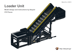
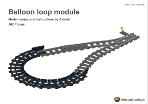
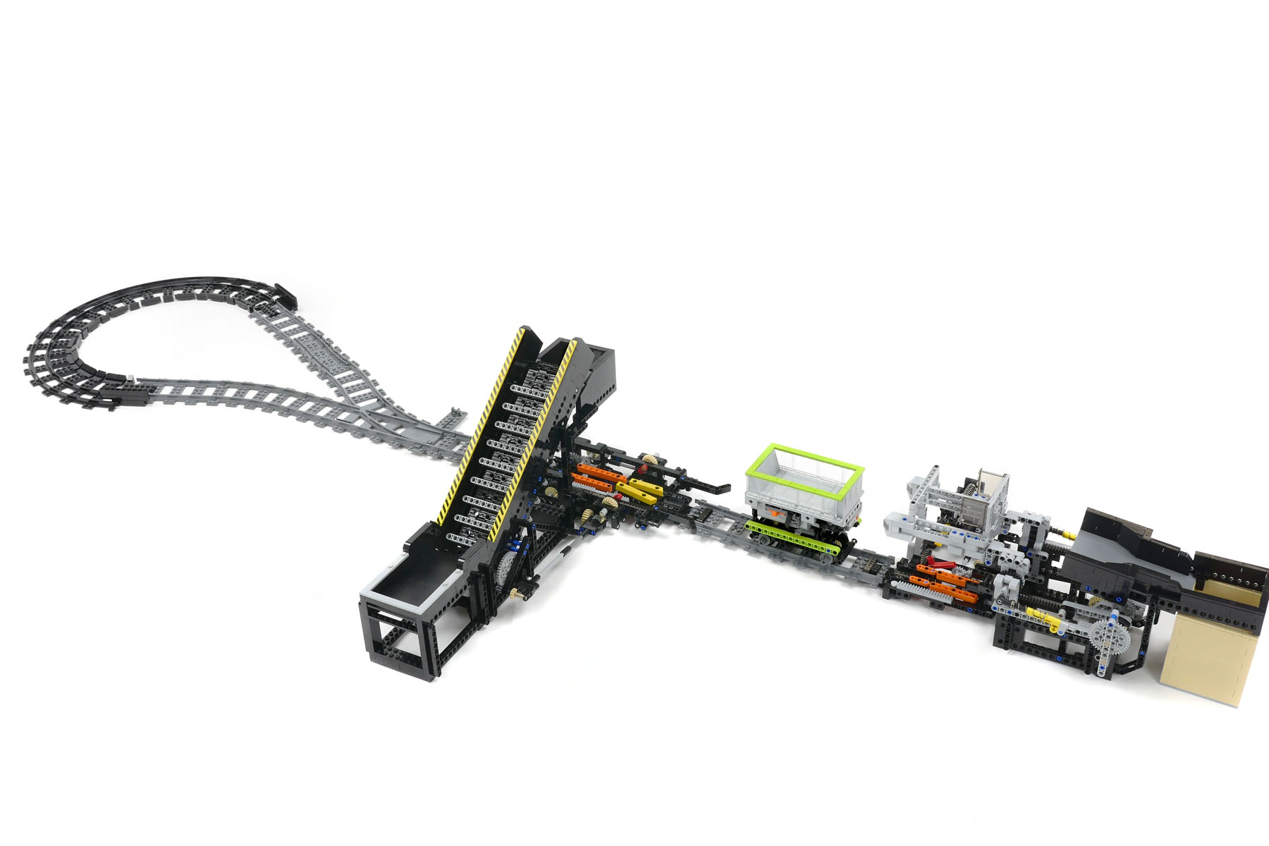
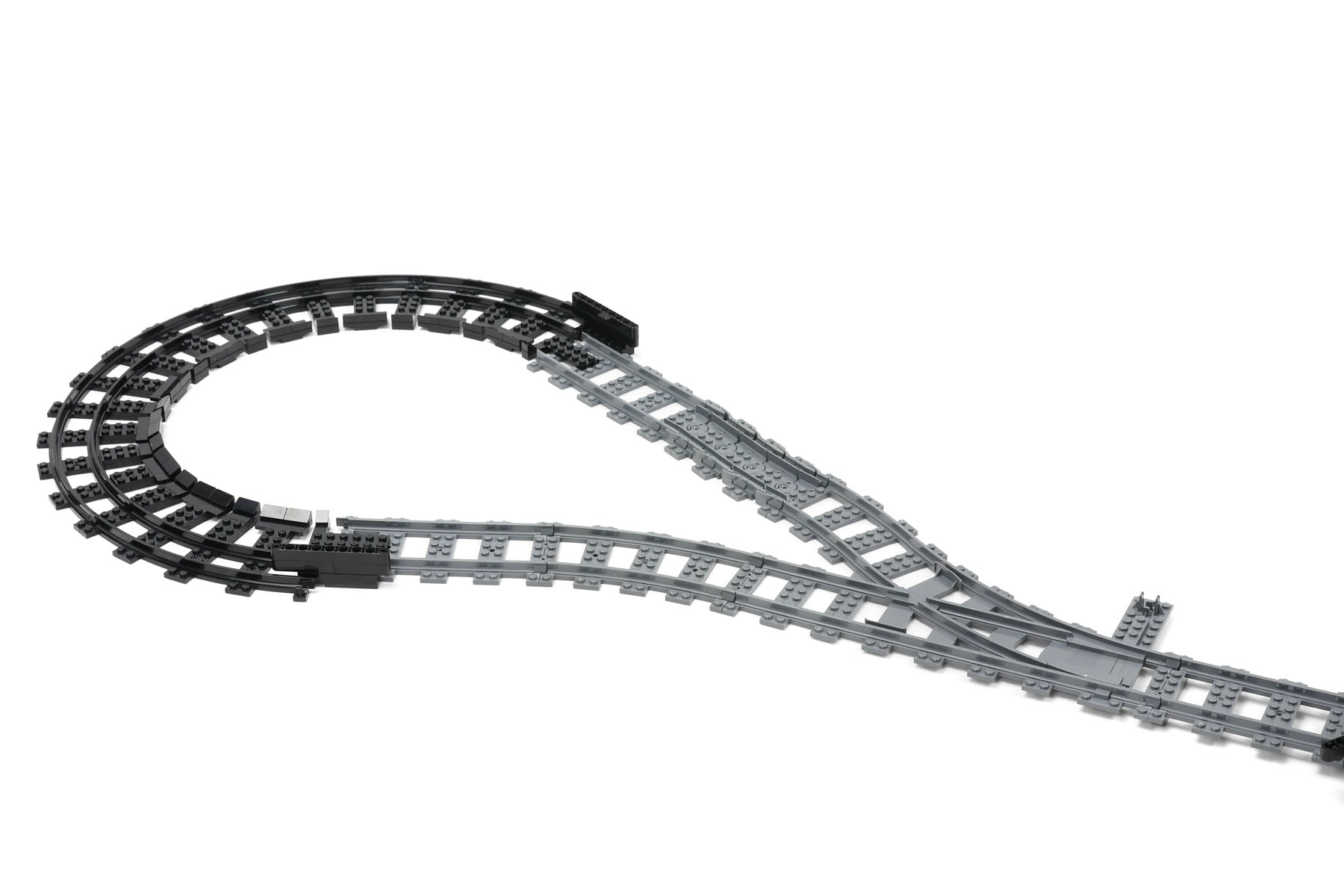
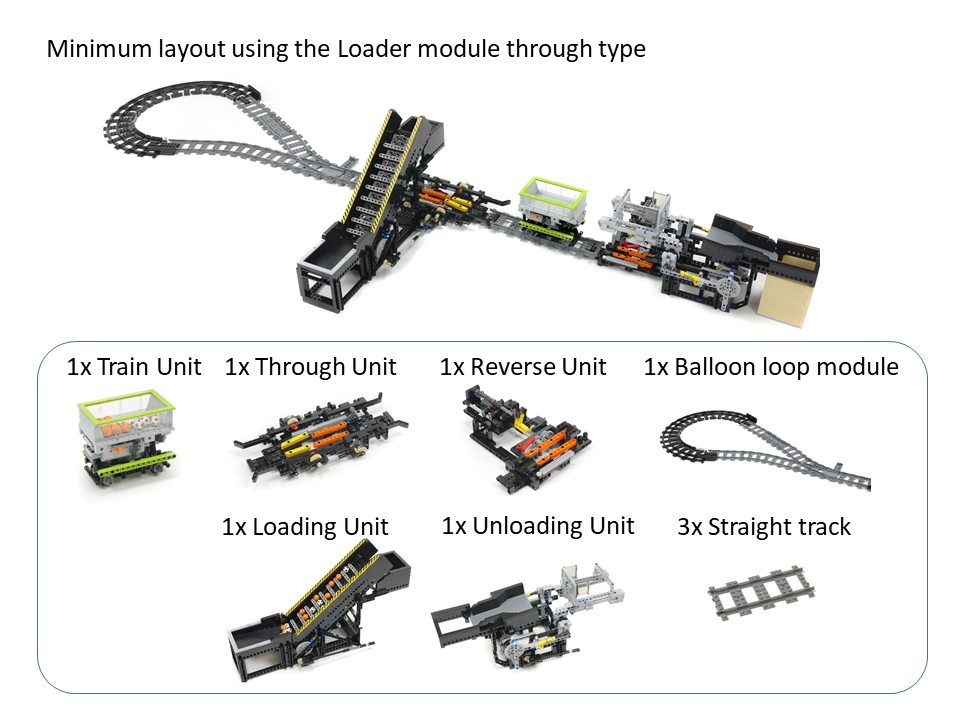
The following photographs show the minimum layout using the Loader module through type. The track of the layout includes a Balloon loop module. Usual rail parts are too large to construct the Balloon loop module, so narrower rail parts are used to make it smaller in size. The layout can be modified to put the Loading Unit inside the Balloon loop module.
I explain the mechanisms of the Through Unit as follows. When a train enters the Unit from the left, the train touches a stopper on the Unit. Then, the train stops and drives an attached Unit (in this case, a Loading Unit). A given amount of gear rotations releases the stopper, and the train starts to leave the Through Unit. When the train enters the Through Unit from the right, the train does not touch the stopper and goes through the Unit.
Components of the minimum layout using the Loader module through type:
Instructions and MPD files for the components of the minimum layout using the Loader module, through type:
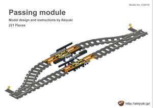
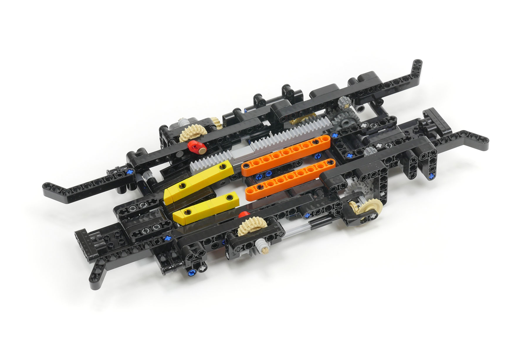
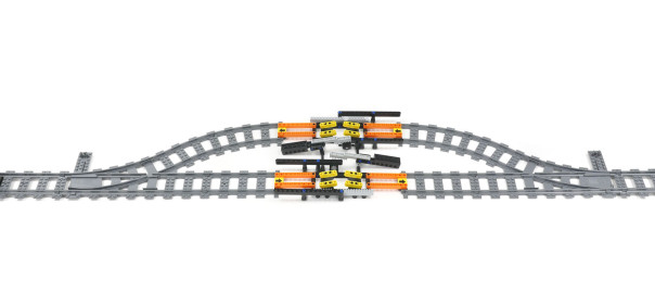
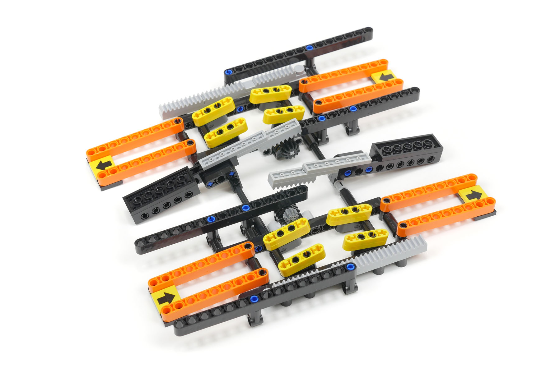
This module acts as a passing track in a railway system. The module enables two trains to run on a single-track railway. Moreover, the two modules also enable three trains to run on a single-track railway.
The module consists of two switch-tracks and a stopper unit as shown in the following photograph.
The stopper unit has two yellow stoppers. The first train is stopped by the stopper. The stopper is invalidated by the incoming train, and the first train is then released. The operation of the passing track is achieved in this way.
This module has structured symmetry. Thus, the simple structure of the module makes it easier to build it.
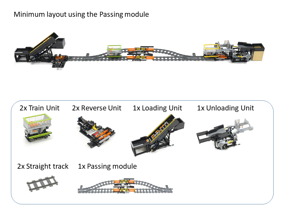
Components of the minimum layout using the Passing module:
Instructions and MPD files for the components of the minimum layout using the Passing module: